Hysteroscopic Image Recording
John L. Marlow
So Others May See
Information can be recorded by text, visual image, or voice. Hysteroscopic findings have traditionally been recorded by text in the operative dictation. This written word evolved through pictorial languages and various writing systems. Modern electronic medical records systems (EMR) are now augmenting these traditional methods. Those in the field of radiology have been leaders in the use of digitized image technology. Electronic medical records now include digitized x-ray films, MRI, CT, and ultrasound images. The digitized hysteroscopic image is also now a part of the patient’s electronic record. High-definition clarity and voice-control versatility have been added. This new video instrumentation has simplified recording an image and has significantly improved its quality. The image is recorded instantly, objectively, and in color. Unlike the dictated word, this image is not filtered by the mind of the dictating surgeon. The photograph records more information than the surgeon records in his or her memory. The truism that “a picture is worth a thousand words” is especially important in an era of expanding medical records that now increasingly include images. Long operative reports in text can be distilled to a few photographs or video. These visual documents provide communication between surgeon and patient, her family, and the referring physician. The hysteroscopic images are accessible in a matter of seconds, any time, any place, to any health provider with the appropriate access systems. These medical images can be viewed by surgeons in hospitals, offices, and at home if need be. The images also play an important role in educating the next generation of surgeons. Some of the uses of hysteroscopic images are listed in Table 20.1.
History
The first image recordings of hysteroscopy were freehand drawings. The surgeon drew a sketch and labeled it after the surgery. The only tools necessary were a pen and paper. The only limitation was the surgeon’s ability to draw. This simple recording method continues to this day. Hysteroscopy publications of the late 1800s included such sketches. Later publications added color paintings of the hysteroscopic finding; these paintings were usually made by artists who accompanied surgeons to the theater and looked over their shoulders (Fig. 20.1). Photography became the next visual recording method added to hysteroscopy. In 1826, Joseph Nicephone Niépce produced what is considered to be the first photograph, which consisted of the roofline visible from his workshop in France. Eight hours of bright sunlight were required to produce this fuzzy permanent image. Louis Daguerre in 1835 improved the process and made it reproducible using silver copper plates coated with an iodine vapor. George Eastman developed the Kodak camera and film in the United States. “Kodak” was chosen because it could be pronounced in all languages. McKellen patented the single-lens reflex camera in 1888. Using this camera, 35-mm film became the highest-quality visual record for hysteroscopy. It is being replaced by electronic image recording.
Television
In the 1980s television image recording was introduced. Hysteroscopic use of television coincided with the manufacture of low-cost chip cameras, sensitive to low light. Hysteroscopists, following their orthopedic associates, performed surgery while viewing the television monitor. Gynecologists remained seated comfortably with the patient in a flat position. A large television monitor image was visible to the entire surgical team. Full-color prints and videotapes of the surgery were easily attainable. Television is now an essential part of hysteroscopy.
Light
To obtain optimum image recording through the hysteroscope, an understanding of the principles of light is necessary. Visible light is generated when energy is added to atoms and subsequently lost in the form of photons. The
color of the visible light will vary according to the source of the light. Color temperature is expressed in degrees Kelvin, equivalent to Celsius degrees plus 273 degrees. Color temperatures of common light sources are outlined in Table 20.2. Tungsten provides an inexpensive source of light. Its filaments emit light at 2,000 Kelvin, the temperature of molten steel, emphasizing red tones. With the addition of halogen, useful light with a temperature of 3,350 K is obtained. Metallic arc and xenon bulbs are capable of producing intense light at 6,000 K. High-intensity 150- to 300-watt bulbs from xenon lamps form the basis of current light sources. Strobe light, in the 5,000 Kelvin range, provides the highest light intensity possible but has become unnecessary with low-light-sensitive cameras. Light intensity decreases with the square of the distance to the object illuminated. Close-up imaging therefore will require less light than panoramic inspection. Most hysteroscopic surgery is performed within 1 inch of the tissue viewed. Dark-colored tissue such as blood absorbs light, whereas white tissue such as synechiae reflects light. White balance controls compensate for variation in color temperatures of the light source.
color of the visible light will vary according to the source of the light. Color temperature is expressed in degrees Kelvin, equivalent to Celsius degrees plus 273 degrees. Color temperatures of common light sources are outlined in Table 20.2. Tungsten provides an inexpensive source of light. Its filaments emit light at 2,000 Kelvin, the temperature of molten steel, emphasizing red tones. With the addition of halogen, useful light with a temperature of 3,350 K is obtained. Metallic arc and xenon bulbs are capable of producing intense light at 6,000 K. High-intensity 150- to 300-watt bulbs from xenon lamps form the basis of current light sources. Strobe light, in the 5,000 Kelvin range, provides the highest light intensity possible but has become unnecessary with low-light-sensitive cameras. Light intensity decreases with the square of the distance to the object illuminated. Close-up imaging therefore will require less light than panoramic inspection. Most hysteroscopic surgery is performed within 1 inch of the tissue viewed. Dark-colored tissue such as blood absorbs light, whereas white tissue such as synechiae reflects light. White balance controls compensate for variation in color temperatures of the light source.
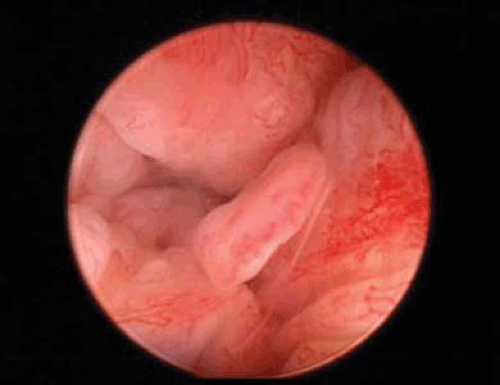 FIGURE 20.1 Video image of polypoid endometrium. |
TABLE 20.1 Uses of Hysteroscopic Images | ||||||||
|---|---|---|---|---|---|---|---|---|
|
TABLE 20.2 Color Temperature of Common Light Sources | ||||||||||||||
|---|---|---|---|---|---|---|---|---|---|---|---|---|---|---|
|
Light Systems
The first method of illuminating the uterine chamber was by sunlight directed into the uterus by mirrors. The surgery could be performed only during daylight, in good weather, and usually outdoors. Candles were used next, but provided poor lighting. Kerosene and alcohol flames were used by the French to light the hysteroscope but this too was abandoned. The flaming lantern posed a hazard to both the patient and surgeon. Thomas Edison developed the incandescent bulb in the late 1800s, and modern lighting techniques for photography began. Nitze attached small light bulbs to the distal cystoscope, which improved the quality and intensity of the light; however, the “hot light” it produced could burn the patient. Gynecologists adapted this cystoscope as their first useful hysteroscope. Electronic flash, developed in 1935, was added to the laparoscope and in turn the hysteroscope. In the 1960s fiberoptic cables were introduced and provided a cold light source. Current illumination systems commonly use 300-watt xenon bulbs (Fig. 20.2).
Light Transmission
Light is transmitted from its source to the hysteroscope by means of a light cable composed of fiberoptic strands. These strands transmit light from its source through the fibers into the uterine chamber. This fiberoptic delivery of light is sometimes called “cold light.” Major improvements in fiberoptic technology were developed in the 1960s as a result of basic research in the aerospace and communications industries. The optical fiber is a special glass, drawn to 10 to 25 μm in diameter, about the diameter of a human hair. Electromagnetic waves that constitute light travel best through regions that have high refractive indices. The center or core of the glass fiber transmits light very effectively. Light is kept inside the fiber by reflections from the outer surface of the fiber. Surrounding this core is a glass with a lower index of refraction referred to as cladding. Light travels within the fiber by reflection from the cladding in a roller coasterlike path. It travels long distances with little loss of light. The light can be deflected in any direction by moving the fiber. Some light is lost at junctions between the cable fibers and the fibers within the hysteroscope. Light loss can also occur within the cable from reflective losses and broken fibers.
Some light is also lost during transmission and is proportional to the length of the cable. Smaller hysteroscopes have fewer light fibers and will limit the amount of light transmitted. Hulka and Reich have provided an illustrated description of endoscopic light optics and television principles.
Some light is also lost during transmission and is proportional to the length of the cable. Smaller hysteroscopes have fewer light fibers and will limit the amount of light transmitted. Hulka and Reich have provided an illustrated description of endoscopic light optics and television principles.
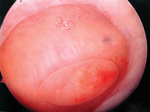 FIGURE 20.2 An endometrial polyp arising from the posterior endometrial wall. The internal tubal os can be seen above the polyp. |
Fiberoptic cables transmit both light and image. They are described as either coherent or incoherent. Cables that have a precise ordered arrangement of the fibers so that any image entering one end will be reproduced on the other end are said to be coherent bundles. This type of cabling is used in flexible hysteroscopes and flexible teaching attachments. Incoherent fiberoptic cables are less expensive to construct and have a random nonordered arrangement of fibers. They are used primarily as light cables between the light source and the hysteroscope. Contact hysteroscopes do not need light cables but use a large-diameter light collection collar to focus light on its distal window. No separate light source or light cable is necessary. Care should be taken with the placement of the ends of light cables with the light source on. The tip may become hot and burn the patient or set the drapes on fire.
Fiberoptic cables are used to transmit laser energy within the hysteroscope. The so-called fiber lasers include neodymium–yttrium-aluminum-garnet (Nd-YAG), xenon, KTP-532, and argon lasers. These lasers deliver an intense energy through a very small fiber. Their diameter measures less than a millimeter. This energy source is useful in small-diameter hysteroscopes with narrow operative channels. Fiber lasers can be transmitted through liquid distention medium regardless of its electrolyte content.
Endoscopes consisting of a single 0.5-mm flexible fiber are now available. This single-strand endoscope transmits light and image through the same fiber. Because of its small caliber, it can be used to inspect the fallopian tube lumen. The small fiber is inserted through the hysteroscope into the internal tubal os and into the proximal tube.
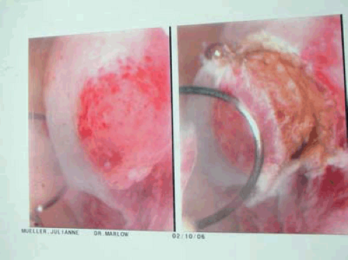 FIGURE 20.3 Digital image showing the tip of a polyp with hemorrhagic changes. A large wire loop first-pass resection is demonstrated. |
Hysteroscope
The hysteroscope is composed of lenses, fiberoptic bundles for lighting, and one or more channels. These channels are used to introduce tools for operative hysteroscopy or for circulating the distending medium. The first hysteroscopes made by Nitze in 1879 consisted of an eyepiece followed by a series of thin lenses separated by large spaces. Professor H.H. Hopkins of the University of Reading in England significantly improved endoscope design by developing the Hopkins rod-lens system in 1966. Following mathematical calculations, he substituted long rod lenses with optically finished ends for the thin lenses. This change produced a brighter image, better resolution and contrast, and a wider field of view. The quality of image records improved with this new hysteroscope. The viewing angles of the hysteroscopes vary from the straight forward-looking hysteroscopes to the fore-oblique hysteroscopes with a viewing angle from 12 to 30 degrees. The angled view is useful for diagnostic hysteroscopy. Figures 20.3, 20.4, 20.5, 20.6 are examples of the fore-oblique, 30-degree, hysteroscope images. This lens system provides the ability to inspect the lateral walls directly instead of at an acute angle. Figure 20.3 demonstrates the lateral endocervical canal image. The dark circle at the bottom of the image is the endocervical canal, seen eccentric with the canal and hysteroscope in alignment. Figure 20.4 shows a heads-on image of the internal os of the fallopian tube as seen with the 30-degree hysteroscope. The identification of this landmark is critical for hysteroscopy sterilization procedures. Some optical distortion is produced with the fore-oblique lenses. This is apparent in Figure 20.5 with the grasping jaws of the forceps appearing to be angled from the ceiling. Figure 20.7 demonstrates stabilizing the videocamera while rotating the 30-degree hysteroscope for inspection with minimal motion of the tip. Figure 20.8 is an image of multiple endometrial polyps and a thickened endometrium. Figure 20.2 shows a single endometrial polyp
with increased vessels at the tip of the polyp, distinguishing it from a fibroid. Figure 20.24 shows the thining of the endometrium in an atrophic postmenopausal state. For operative hysteroscopy, some surgeons prefer a forward-viewing hysteroscope because it introduces minimal distortion.
with increased vessels at the tip of the polyp, distinguishing it from a fibroid. Figure 20.24 shows the thining of the endometrium in an atrophic postmenopausal state. For operative hysteroscopy, some surgeons prefer a forward-viewing hysteroscope because it introduces minimal distortion.
Related posts:


Stay updated, free articles. Join our Telegram channel

Full access? Get Clinical Tree


