Chapter 3 Radiologic Issues and Radiation Safety during ERCP
The scope and practice of endoscopic retrograde cholangiopancreatography (ERCP) has evolved over the past 2 decades. First, with the advances in magnetic resonance cholangiopancreatography (MRCP) in both academic and private settings alike, nearly all ERCP is therapeutic.1,2 Increased complexity and emerging capabilities of therapeutic ERCP often lead to longer procedure times and the potential for increased radiation exposure to patients, endoscopists, nurses, and other personnel involved in the procedure. Coupled with the emergence of endoscopic ultrasound (EUS) for diagnostic and therapeutic applications, more than ever the shift in practice patterns heightens the importance of communication between the endoscopist and radiologist in order to provide the patient with the best possible and most consistent interpretation of images acquired during ERCP, and with physicists to ensure patient safety.3 This chapter focuses not only on techniques of image acquisition during ERCP using examples of pathology (discussed in depth elsewhere in the book) to demonstrate imaging principles, but also on essential radiation safety considerations for patients and personnel during the procedure.
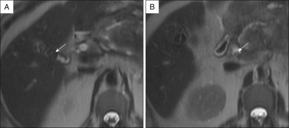
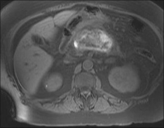
Prior to the ERCP procedure, review of other imaging studies (computed tomography [CT], magnetic resonance imaging [MRI], or ultrasound) is often helpful to plan and expedite the case. Depending on the planned procedure, particularly when drainage is anticipated, it is important to recognize that imaging information varies with the modality being used. Distal common bile duct (CBD) stones are difficult to visualize in a nondilated system by transabdominal sonography, but are well depicted on MRCP. The complexity of pancreatic collections is better identified with MRI compared to CT, and although both are comparable for early assessment of necrosis and inflammation in acute pancreatitis, MRI, even without benefit of intravenous (IV) contrast enhancement, has advantages over CT in detecting bile duct lithiasis (Fig. 3.1) and pancreatic hemorrhage (Fig. 3.2).4 If therapeutic endoscopic interventions are intended, availability of the pancreatobiliary surgeon or interventional radiologist for treatment of potential adverse events or participation in combined procedures is desirable. In our practice, discussion during multidisciplinary conferences or evaluation of the patient with pancreatic pathology in multidisciplinary clinics is beneficial for diagnostic and therapeutic planning. The patient’s history of medical allergies, including to contrast material, should be ascertained during the consent process.
Fluoroscopic Imaging Systems
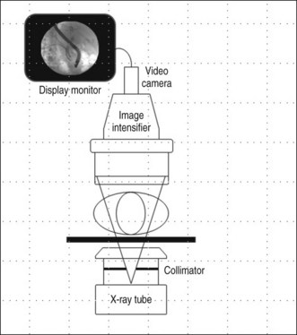
Real-time image guidance for ERCP is most commonly provided by fluoroscopy. The basic components of a fluoroscopic system include an x-ray tube, generator, image receptor, and video system for image display and recording (Fig. 3.3). Modern fluoroscopy systems incorporate multiple operational modes and configurations. Therefore it is important that physicians using fluoroscopy have adequate knowledge of its appropriate use.
Most fluoroscopy systems include a display of patient dose (required for equipment manufactured in the United States since 2006). The dose parameter displayed is the entrance skin air kerma with units of milligray (mGy). During fluoroscopy, the air kerma rate is displayed and after fluoroscopy, the patient’s cumulative air kerma is shown. Typical air kerma rates for an average-sized adult abdomen range from 20 to 60 mGy/min. Regulatory requirements limit the maximum air kerma rate to 88 mGy/min in the normal mode. Fluoroscopy equipment may include high-level control mode, which can be activated to allow for higher exposure levels, up to 176 mGy/min. For ERCP procedures, Buls et al.5 report a median cumulative entrance air kerma of 271 mGy (maximum 1180 mGy).
Radiation Dose Management in Fluoroscopic Procedures
The endoscopist has control over multiple parameters that can be adjusted to alter patient radiation dose during a fluoroscopic procedure. Though the risk of radiation injury is low, deterministic effects (including skin burns and cataract formation) and stochastic effects (increased risk of cancer) are possible. Deterministic injuries occur only after the radiation dose to the tissue exceeds a given threshold dose. For fluoroscopic procedures, patient skin injury may occur. A threshold dose of 2000 mGy results in transient erythema, with more severe effects (including epilation and desquamation) resulting from higher dose levels. Though a single ERCP procedure is not likely to reach the threshold dose level for skin injury, if patients have had fluoroscopic exposure in the same anatomic area in the past 60 days, the total skin dose should be evaluated and actions taken to minimize dose to that entry area should be considered if needed. Additional information on radiation injury can be found in several recommended reviews.6–8 Due to the potential of radiation injury, care must be taken to minimize radiation exposure when performing procedures where fluoroscopy is used. Dose optimization requires attention to several basic principles summarized below.
The displayed patient cumulative radiation dose should be monitored throughout the procedure. Postprocedure, the final dose value should be recorded in the patient’s medical record. This information is necessary for monitoring dose to patients receiving multiple procedures over time. Monitoring and recording of procedure doses also helps endoscopists maintain awareness of radiation dose concerns. Similarly, monitoring of personnel radiation exposure is essential to ensure worker safety. Specific protocols for monitoring will vary by facility as determined by the facility radiation safety officer. Radiation monitoring may use a single dosimeter worn at the collar level outside a protective apron or two dosimeters, one worn at the collar and the other worn under a protective apron. For accurate estimation and reliable tracking of occupational dose, dosimeters should be worn and exchanged consistently. The recommended annual dose limit for personnel is 50 mSv whole body and 150 mSv to the lens of the eye.9
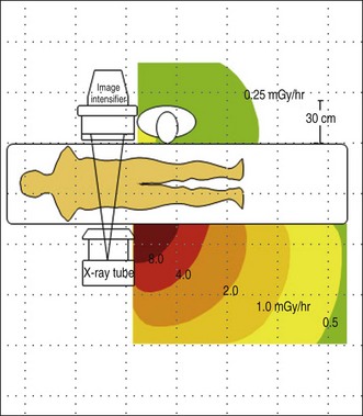
Figure 3.4 shows a representative scatter isodose plot for a C-arm fluoroscopy configuration with the x-ray tube positioned under the table. Note that radiation intensity is concentrated in the area below the procedure table near the x-ray tube. Though x-ray tube leakage results in a small amount of radiation released from the sides of the x-ray tube, scattered radiation levels are substantially higher. This distribution is caused by higher levels of scattered x-rays produced at the primary x-ray beam patient input port. Forward scattered x-rays from the first few centimeters of tissue depth are heavily attenuated by the rest of the patient tissue, resulting in lower radiation levels in the region back near the image receptor. The intensity of scatter radiation for an over-table x-ray tube fluoroscopy system is shown in Fig. 3.5 and a lateral projection is shown in Fig. 3.6.
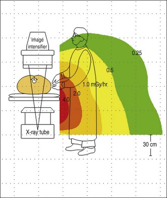
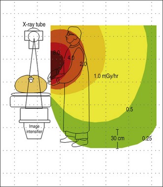
Fig. 3.5 Scatter radiation isodose plot for an over-table x-ray tube fluoroscopy system.
(Author sketch.)
Occupational Ionizing Radiation Exposure
To minimize occupational exposure, personnel should be aware of the locations in the procedure room where scattered radiation levels are highest so that they can avoid these areas. In a controlled, phantom study of radiation doses to personnel during ERCP, Johlin et al.10 described that largest doses are received by the person at the head of the table, generally the nurse who monitors the patient and administers drugs. The next highest dose is received by the endoscopist, who stands at the right-hand corner of the fluoro table, and the lowest dose is received by the assistant who stands alongside the endoscopist at the level of the patient’s abdomen. The low dose received by the assistant at the patient’s abdomen is explained by the use of vertically oriented lead drapes that attach to the fluoro tower and diminish the amount of scatter radiation. When possible, move back from the exposed area of the patient, as the scatter levels fall off rapidly with distance. For C-arm fluoroscopy systems, the x-ray tube should be placed under the patient table. When the C-arm is angled or positioned horizontally, personnel should stand nearest the image receptor where scatter levels are lower. Note that for stationary over-table x-ray tube fluoroscopy systems, the highest scatter radiation intensity will be directed toward the operator’s upper body and head. As a result, additional personnel protection measures may be needed if over-table x-ray tube fluoroscopy systems are used routinely.
All personnel in a procedure room during fluoroscopy must wear a protective garment unless they are positioned completely behind a radiation shield. Radiation protective apparel is available in 0.25- to 1-mm lead-equivalent thickness. In most areas, regulations require that a thickness of at least 0.5-mm lead-equivalent be used, which attenuates more than 90% of scattered x-rays that strike it. Different designs are available, including aprons with front coverage only, aprons that wrap around the body, and two-piece garments with vest and kilt. If there is potential for personnel to have their backs to the patient during the procedure, a wraparound or vest and kilt garment should be worn. Whatever design is selected, it is important to ensure that the garment fits properly with adequate coverage at the neckline and armholes. Due to the heavy weight of protective aprons constructed from lead, lightweight lead composite or lead-free models are being developed. Aprons made from these materials, including barium, tungsten, tin, and antimony, provide the same attenuation as an equivalent thickness of lead at approximately 30% of the weight.11
Thyroid shields are typically an optional radiation protection tool. They are recommended for personnel who receive collar radiation monitor readings over 4 mSv per month.9 Weight and inconvenience to the wearer are relatively minimal, so thyroid protection is also commonly used by workers receiving lower exposure levels. It should be noted that the use of thyroid shields becomes less critical for personnel over 40 years of age since the risk of radiation-induced thyroid cancer is reduced significantly with age.
Until recently, it has been generally accepted that radiation-induced cataracts do not form below a threshold lens dose of 2 to 5 Gy for fractionated exposure. This threshold provided the basis for the maximum permissible dose of 150 mSv per year for the lens. However, new data on the radiosensitivity of the eye indicate that the threshold dose may be significantly lower and current dose limit recommendations are currently being reassessed.5 Therefore careful attention to radiation protection of the eye is warranted to minimize cataract risk. This is particularly important for physicians who routinely perform fluoroscopy procedures with over-table x-ray tube systems. Protective shielding to reduce radiation exposure to the eye from scatter includes leaded eyewear and ceiling-suspended shields.
Related posts:


Stay updated, free articles. Join our Telegram channel

Full access? Get Clinical Tree


