Fig. 8.1
Illustration of optimal patient position for MIS-TG. The pt is positioned on a split-leg table allowing the primary surgeon to stand between the patient’s legs and two assistants to stand on either side of the patient
Port placement for MIS-TG follows the same principles as for any laparoscopic or robotic procedure, which includes placement of the camera port at a distance of 15–20 cm from the target anatomy, and placement of ports at least 5 cm apart for laparoscopic TG (LTG) and at least 8 cm apart for RTG. While multiple variations of port placement have been described, the placement illustrated in Fig. 8.2 is recommended.
Fig. 8.2
Illustration of preferred port placement for MIS-TG. A 12 mm port is placed in the midline near the umbilicus. This port is usually above the umbilicus but the final position should be determined by measuring 15–20 cm from the target anatomy. Two additional ports are placed on the patient’s left side. These are 8 mm ports for RTG or 5 mm ports for LTG. A 12 mm port is placed on the patient’s right mid-clavicular line. For RTG, an 8 mm robotic port is placed within this 12 mm port and can be temporarily removed / reinserted as needed. Finally, a 5 mm assistant port is placed on the right side approximately at the anterior axillary line. All ports should be 5–8 mm apart from each other
Pneumoperitoneum is established via a Veress needle placed off the left costal margin or via an optical viewing trocar. A 10/12-mm trocar is then placed in the midline above or below the umbilicus depending on the patient’s body habitus, but with port placement positioned about 15–20 cm from the target anatomy. In the majority of cases, the infraumbilical position is the best trocar position for total gastrectomy, since it is far enough in the caudal direction for omentectomy and the jejunojejunostomy anastomosis, while still providing sufficient reach to and visualization of the hiatus and distal esophagus. For RTG, two additional 8-mm robotic ports are then placed on the left side, at least 8 cm from each other and slightly offset from the plane of the camera port. An additional 12-mm port is placed in the right midclavicular line. This is the port that will be used for stapling and specimen extraction. For RTG, an 8-mm robotic port is placed within this 12-mm port. A 5-mm assistant port is placed further laterally on the right side, approximately at the anterior axillary line. Placement of a Nathanson liver retractor, via a small subxiphoid stab-wound incision, facilitates secure retraction of the left lateral lobe of the liver and excellent exposure of the esophageal hiatus.
The abdomen is explored for adhesions and for any evidence of peritoneal or metastatic disease. If the lesion is not appreciable on the extraluminal surface, an endoscope is passed to verify location of the lesion. For gastroesophageal junction tumors, the distal esophagus and Z-line should be carefully examined to localize the proximal extent of the lesion. It is critical to ensure that an adequate esophageal resection margin (2–4 cm from the lesion) can be obtained from the transabdominal approach. Once this is confirmed, the patient is placed in reverse Trendelenburg to approximately 45°. For RTG, the robot is docked from directly over the patient’s head. Arms 1 and 3 are docked to the left-sided ports and arm 2 is docked to the right-sided port within the larger 12-mm port (Fig. 8.3). A fenestrated bipolar grasper is placed in arm 2 and an energy sealant device or monopolar scissors is placed in arm 1. Grasping forceps, preferably Cadiere or Prograsp (Intuitive Surgical), are placed in arm 3.
Fig. 8.3
Illustration of robot position for RTG. The robot is docked from directly over the patient’s head
Omentectomy
The procedure commences by retracting the greater omentum cephalad and locating the transverse colon. The omentum is carefully taken off the colon in the avascular plane, proceeding towards the splenic flexure. With careful dissection, the plane between the omentum and the transverse mesocolon is identified and the lesser sac is entered. Visualization of the posterior wall of the stomach confirms entry into the lesser sac. The posterior wall of the stomach is then grasped by the bedside assistant on the patient’s right side and is retracted anteriorly and to the right (Fig. 8.4). The omentectomy is carried up towards the spleen allowing visualization of the short gastric vessels, which are ligated with an energy sealant device under direct visualization. This maneuver provides exposure up to the left crus of the diaphragm. The peritoneum overlying the left crus is incised with the energy sealant device, which should allow the crural muscle fibers to be visible. Gentle blunt dissection along the crus exposes the posterolateral aspect of the esophagus. If the port placement does not allow for reach to the esophageal hiatus, the bedside assistant may push the ports further into the abdominal wall, which can then be retracted again for the distal part of the resection.
Fig. 8.4
Illustration of the view provided when the posterior wall of the stomach is grasped and elevated. This is a key maneuver in MIS-TG
Then, the posterior wall of the stomach is grasped by an assistant on the patient’s left side or utilizing the third arm of the robot in RTG and is retracted toward the patient’s left shoulder. The omentectomy then proceeds toward the hepatic flexure of the colon and is completed. The omentum can be placed in the left upper quadrant on the anterior wall of the stomach at this point.
Greater Curvature Dissection
The posterior attachments between the stomach and pancreas are then divided sharply or with an energy sealant device in the direction of the pylorus. The right gastroepiploic vessels are identified and dissected circumferentially at the level of the superior border of the pancreas at their point of origin from the gastroduodenal vessels (Fig. 8.5). If the linear stapler is to be used, arm 2 of the robot and its 8-mm port is removed from the larger 12-mm port and the linear stapler is used.
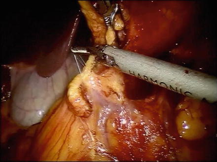
Fig. 8.5
Photo of the origin of the right gastroepiploic vessels. The right gastroepiploic vein often shares a common trunk with the right colic vein (Henle’s trunk)
Division of Proximal Duodenum
Attention is then turned towards the suprapyloric region. The gastrohepatic attachments are incised with an energy sealant device in robot arm 1. The right gastric artery is identified and is ligated at its base. The lymphatic tissues along the proper hepatic and common hepatic artery are swept medially toward the specimen and a window is created at the level of the pylorus. The posterior aspect of the pylorus and proximal duodenum is gently elevated off the retroperitoneum with a combination of blunt dissection and use of the energy sealant device. An endovascular linear stapler with a blue or green load is then introduced and the proximal duodenum is stapled and divided just distal to the pylorus. We prefer to use bioabsorbable staple line reinforcement on the duodenum (Fig. 8.6).
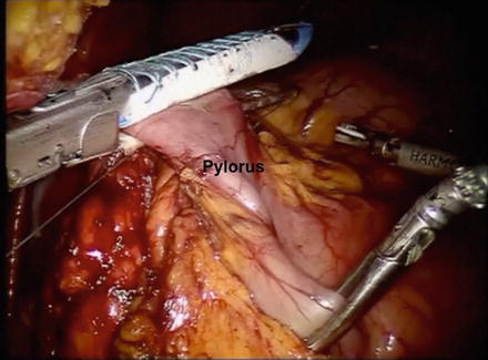
Fig. 8.6
Photo of the proximal duodenum being divided just distal to the pylorus. A linear stapler with bioabsorbable reinforcement is preferred
Modified D2 Lymphadenectomy (D1 + β)
Next, the stomach can be placed in the left upper quadrant to facilitate exposure of the D2 lymph nodes (Fig. 8.7). The dissection that was started previously along the proper hepatic artery is continued along the common hepatic artery toward the celiac axis and proximal splenic artery. The left gastric vein and artery are identified at the celiac axis and all surrounding lymph nodes carefully swept up en bloc with the specimen. The vessels are then divided at their origin at the celiac axis with the endovascular linear stapler or with clips.
Fig. 8.7
Illustration of the lymph nodes beyond the D1, perigastric nodes, that need to be removed in a modified D2 lymphadenectomy
Division of the Distal Esophagus
The gastrohepatic attachments are then further incised up to the level of the esophageal hiatus with the energy sealant device. The level 1 and 3 lymph nodes are dissected with the proximal stomach up to the right crus of the diaphragm and esophagus. The peritoneal fat and fat pad overlying the esophagus are opened with the energy sealant device and the distal esophagus is circumferentially dissected. The distal esophagus is then divided with a reticulating linear stapler (blue load).
Specimen Retrieval
At this point, the specimen is placed in a specimen retrieval bag and is removed via the umbilical port site which is enlarged about 1.5 cm after changing the camera position to the right-sided 12-mm port site. The camera port is then replaced and the 8-mm robotic port attached to arm 2 is placed within the 12-mm right-sided port site after returning the camera to its initial position at the umbilical port. The proximal margin is marked with a stitch and is sent for frozen section analysis to confirm microscopic clearance of disease. Attention is then turned to the reconstruction.
Reconstruction
Roux-en-Y esophagojejunostomy is performed for restoration of gastrointestinal continuity. The colon is elevated in a cephalad direction and the ligament of Treitz (LOT) is identified. A mobile piece of jejunum approximately 30–40 cm downstream from the LOT is selected based on mobility and tension-free reach to the esophageal hiatus and is used for reconstruction. The jejunum is then transected with a linear stapler with a blue load and the Roux limb is measured out to about 60–70 cm at which point the jejunojejunostomy is created with another firing of the linear stapler with a blue load. The resultant enterotomy is closed with a 2-0 silk running suture. The Roux limb is then prepared for esophagojejunostomy, which is an end-to-side anastomosis created with a 25-French circular stapler. To facilitate this, we prefer to use a transoral anvil (OrVil, Covidien) (Fig. 8.8). This device is an anvil connected to a nasogastric tube. The device is passed transorally usually by the anesthesiologist. Once the tip of the tubing is visible against the stapled end of the distal esophagus, a small esophagotomy is made with electrocautery to facilitate passage of the tubing through the wall of the esophagus. Care is taken to prevent contact between the contaminated tubing and the abdominal viscera. The tubing is grasped and pulled out of the abdomen via the 12-mm port. Robot arm 2 is undocked to facilitate removal of the tube in RTG. The tubing is then gently detached from the end of the anvil and is removed through the 12-mm port. The stapler is inserted into the Roux limb after removing the staple line with the energy sealant device. The anvil and spike are then connected and the stapler is fired. The open end of the Roux limb is then closed with a linear stapler.
 < div class='tao-gold-member'>


Only gold members can continue reading. Log In or Register to continue
Related posts:


Stay updated, free articles. Join our Telegram channel
Full access? Get Clinical Tree
