Instrumentation for Hysteroscopy
Michael S. Baggish
Hubert Guedj
Selection of the proper and most appropriate instruments is one of the keystones for the performance of a successful hysteroscopic examination. The prospective hysteroscopist is often overwhelmed by the variety of instruments available in the marketplace and may be confused when presented with the multitude of specialized endoscopes, sheaths, and accessories offered by instrument manufacturers and detail salespersons. The question “What best fits my needs and pocketbook?” should always be asked before purchasing equipment. Obviously, a logical chronology of learning and experience should be followed to master any new technique. To jump headlong from no hysteroscopic experience into complex electrosurgical or laser hysteroscopic surgery without intermediary steps is both foolish and reckless. Likewise, to attempt hysteroscopy and expect optimal results with makeshift equipment such as urethroscopes, cystoscopes, or laparoscopic insufflators is to court the unexpected. Purely and simply, fine, skilled procedures should be performed with precision instrumentation. Diagnostic skills and mastery in learning to orient oneself within the intrauterine milieu must always precede intrauterine operative intervention. In fact, every operative hysteroscopic procedure should be immediately preceded by a thorough diagnostic scan of the endometrial cavity.
The two major elements of a hysteroscope are the telescope or lens and the sheath. Important optical components at the proximal end of the telescope include a prism used to form an outright image of the object, an eye lens to magnify this image, and an optical window provided for viewing.
Two features pertinent to all endoscopes are, first, the angle of view, which depends on the angle subtended by the objective lens and which can vary from a straightforward view (0 degrees or 180 degrees), fore-oblique view (30 degrees or 150 degrees), lateral view (70 degrees or 110 degrees), right angle view (90 degrees), to a retrospective view (120 degrees or 60 degrees); and, second, the field of view, which is the peripheral coverage of the optical system or how much of the object is seen at a given distance from the object. The field of view varies according to the refractory index of the medium used to distend cavities.
Panoramic Telescopes
All endoscopes have similar characteristics and a similar purpose, which is to obtain an undistorted and clear visualization of the area observed. The most important component of the endoscopic system is the telescope, which transmits the light for illumination and carries the image to the viewer’s eye. The optical features of the telescope include lenses, prisms, glass windows, and fiber optics. There are three basic endoscopic optical systems used with rigid endoscopes: the bead-lens system, the rod-lens system, and the graded index system. Bead-lenses are made of glass no thicker than their diameter, whereas in the rod-lens system designed by Hopkins, the lenses’ thickness is larger than the actual diameter, with very small spaces in between. This newer rod-lens system provides a larger viewing angle and a brighter image, which is transmitted by an array of long cylinders of superior optical-quality glass. The third optical system is the graded index system (GRIN), in which the entire system includes a slender rod of glass with a progressively increasing refractory index from the axis to the periphery. This latter system is used with very slender optical systems.
A new system using fiberoptic imaging technology has been introduced, particularly with the fused-image bundle, that permits better use of light, therefore permitting a decrease in the size of telescopes without impairing resolution (Fig. 11.1). The higher the refractory index, the smaller the field of view.
With the use of fiberoptics, potent lights can be transmitted through an appropriate light source fountain to the endoscope without producing excessive heat or breakage of distal bulbs. The many thousands of small glass fibers (10 μm) with a high refractory index core and low index cladding produce a compact system that delivers brighter light efficiently with minimal loss. These optical components have resulted in high-quality, small-diameter telescopes capable of producing high-quality images with wide fields of view.
The telescopes used for operative hysteroscopy in general have an outer diameter of 4 mm with a fore-oblique
view (25 degrees to 30 degrees). The depth of field is 2 to 3 cm, and only slight magnification (×34 to ×35) is obtained with these telescopes, with the same distending medium used. Newer instruments have been developed, however, to permit increased magnification by turning a knob at the proximal end of the telescope. The length of the telescope is standard, 30 to 35 cm, with the exception of the microhysteroscope (Hamou), which has an offset arm attached laterally to the proximal end of the hysteroscope for additional magnification of ×60 and ×150 with a contact technique.
view (25 degrees to 30 degrees). The depth of field is 2 to 3 cm, and only slight magnification (×34 to ×35) is obtained with these telescopes, with the same distending medium used. Newer instruments have been developed, however, to permit increased magnification by turning a knob at the proximal end of the telescope. The length of the telescope is standard, 30 to 35 cm, with the exception of the microhysteroscope (Hamou), which has an offset arm attached laterally to the proximal end of the hysteroscope for additional magnification of ×60 and ×150 with a contact technique.
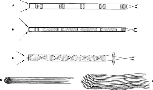 FIGURE 11.1 Endoscopic optical systems used in rigid endoscopes. A: The bead-lens system, in which the lenses are thin in comparison with their diameters and separation. B: The rod-lens system designed by Hopkins, in which a lens’ thickness is large compared with its diameter and the airspaces are small. C: The graded index (GRIN) lens system, in which the entire system consists of a slender rod of glass; the refractory index decreases from the axis to the periphery according to a specific mathematical relationship. D: Fused image bundle. E: Flexible image bundle. |
Modern panoramic telescopes are rigid instruments that consist of an optical component and an illumination (lighting) mechanism (Fig. 11.2). The resolution (small detail or point-to-point discrimination) of rigid instruments far exceeds that of fiberoptic, flexible instruments. The telescope can be subdivided into an eyepiece, a barrel, and a terminal (objective) lens (Figs. 11.3 and 11.4). Most commonly, the inner-barrel structures are encased in stainless steel. Within this steel cover are located groups of lenses or rods separated by air spaces. These constitute the transmission lens system. Surrounding the optical components are glass fiberoptic bundles that transmit cold light by way of a fiberoptic cable from a remote light generator. Generally speaking, the 4-mm outer diameter of the telescope is the narrowest diameter that can provide an optimally bright, clear, wide-angle view of an object together with a high-intensity light shower. Although telescopes of smaller diameters are marketed, they all suffer from shortcomings of lower light capacities and lesser clarity. Nevertheless, telescopes 2 to 3 mm in diameter coupled to small covering sheaths do permit easier entry into the cervical canal and are advantageous for office hysteroscopy. Practically, however, the 4-mm telescope is the instrument of choice. The viewing angles most commonly available are either 0 degree (straight on) or 30 degree (offset) (Fig. 11.4). Selection of these angles is mostly a matter of personal preference. For the beginner, the 0-degree telescope is easier to use because orientation is similar to that of normal vision (Fig. 11.5A).
Additionally, during operative hysteroscopy a long, panoramic view of an instrument is possible only with the 0-degree lens. Although the 30-degree lens is well adapted to the resectoscope electrode, the view is lost when the device is fully extended out and away from the sheath. The 30-degree telescope permits a rapid, dextrous evaluation of the anterior
walls, posterior walls, and cornual recesses (Fig. 11.5B). Simply rotating the telescope slightly to the right or left permits the endoscopist to see the tubal ostia. In comparison, the same view with a 0-degree scope is possible by angulating the instrument to the left or right. One must remember that depth perception is limited substantially because the sighting is monocular rather than binocular.
walls, posterior walls, and cornual recesses (Fig. 11.5B). Simply rotating the telescope slightly to the right or left permits the endoscopist to see the tubal ostia. In comparison, the same view with a 0-degree scope is possible by angulating the instrument to the left or right. One must remember that depth perception is limited substantially because the sighting is monocular rather than binocular.
 FIGURE 11.2 Diagnostic hysteroscopic sheath with coupled telescope is shown. The telescope is 4 mm OD and provides a straight-on field of vision, i.e., 0 degrees. The sheath is a mere 55 mm OD. |
Because most hysteroscopists couple an endoscopic television camera to the lens to view from a video monitor rather than directly from the telescopic eyepiece, the image seen is both magnified and two-dimensional (i.e., minimal to no depth). Additionally, one should bear in mind, regardless of whether diagnostic or operative hysteroscopy is contemplated, that the telescope remains constant. Finally, these instruments are focused at infinity and therefore give an image that is smaller than actual size when positioned away from the object and, correspondingly, magnified when moved closer to the object. Therefore it is impossible to determine accurate measurements without a frame of reference within the same viewing.
The quality of instruments may be judged by viewing a detailed object, for example, a piece of multicolored printing, and noting the brightness and clarity of the image viewed, the diameter of the field seen at various reference distances, and the intensity of illumination in a dark space (e.g., inside a double-thickness bag or opaque container).
Several varieties of telescopes are available (Fig. 11.6). These instruments differ mainly in the objective lenses. These devices may practically range from 0 degrees to 70 degrees (Fig. 11.6). Focusing telescopes function somewhat like a microscope, i.e., permitting panoramic as well as macro or close-to-object magnified viewing (Fig. 11.7). These instruments achieved a degree of popularity in the 1980s and early 1990s; however, they have been largely replaced by fixed-focus rigid telescopes as well as flexible, fiberoptic telescopes.
Miniaturization of endoscopes has been made possible by advanced optical technology that permits better light use and increased resolution. Endoscopes with less than 3-mm outer diameter are being tested in an effort to simplify ambulatory procedures. These very small telescopes include flexible fiberoptic devices as well as 3-mm outer diameter (OD) rigid telescopes fitted to 4-mm OD sheaths (Fig. 11.8A).
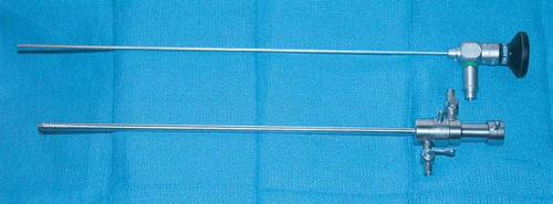 FIGURE 11.3 Telescope (top) and diagnostic flushing sheath (bottom). The objective lens of this telescope is 0 degrees. |
Sheaths
Before entering a hollow organ such as the uterus, the telescope must be fitted to a sheath through which a distending medium can be infused to provide necessary distention for panoramic viewing. To provide reasonable clearance for a 4-mm telescope, the typical diagnostic sheath measures 5 mm OD. Whether the sheath measures 300 mm in length or the
240 mm frequently used with microhysteroscopes, the diameter (5 mm) is usually the same and the ease of entrance into the uterus is identical. Diagnostic sheaths ranging from 3 to 5 mm are well suited for office hysteroscopy using gaseous distending media, but instillation of liquid media may be difficult because of the small clearance space between the endoscope and the inner wall of the sheath (Fig. 11.9). Entry into the interior cavity of the sheath is provided by a single or double stopcock with a Luer-lock fitting. Some diagnostic sheaths are equipped with two stopcocks to facilitate media input and output coupling from either right or left sides.
240 mm frequently used with microhysteroscopes, the diameter (5 mm) is usually the same and the ease of entrance into the uterus is identical. Diagnostic sheaths ranging from 3 to 5 mm are well suited for office hysteroscopy using gaseous distending media, but instillation of liquid media may be difficult because of the small clearance space between the endoscope and the inner wall of the sheath (Fig. 11.9). Entry into the interior cavity of the sheath is provided by a single or double stopcock with a Luer-lock fitting. Some diagnostic sheaths are equipped with two stopcocks to facilitate media input and output coupling from either right or left sides.
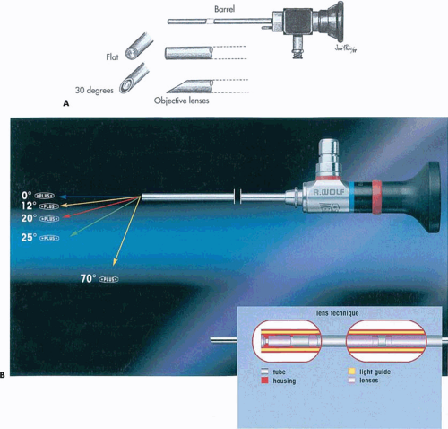 FIGURE 11.4 A: The most common objectives are 0 degrees (flat) and 30 degrees (offset). B: The relative direction of view via the telescope by an observer. The objective lens degrees and angles are shown in different colors. The inset shows the rod lens and fiberoptic system. |
New continuous-flow hysteroscopes designed for hysteroscopic purposes with a 4- to 5-mm OD sheath have been introduced to permit low-viscosity fluids to be used for uterine distension. However, occasionally cervical dilatation may be required, particularly in nulliparous or postmenopausal patients (Fig. 11.10). These new small-diameter continuous-flow hysteroscopes with a 5-French operative
channel have been introduced and manufactured by most instrument companies, such as: Storz, Olympus, ACMI, Wolf, and so on (Fig. 11.10).
channel have been introduced and manufactured by most instrument companies, such as: Storz, Olympus, ACMI, Wolf, and so on (Fig. 11.10).
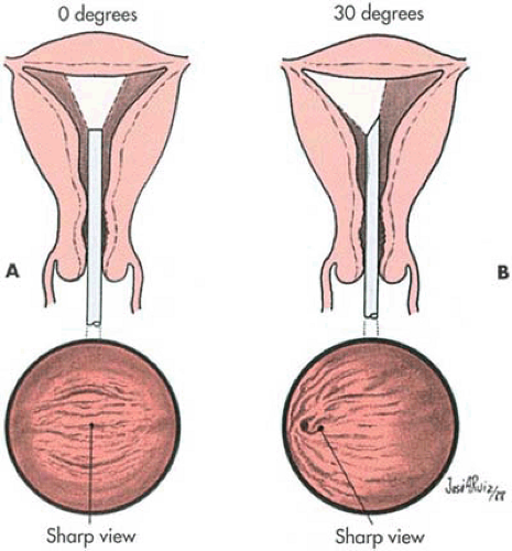 FIGURE 11.5 Example of 0-degree view (A) and 30-degree view (B). |
Quality machining and construction should be evaluated. The terminus of the endoscope should fit flush with the end of the sheath. The stopcock should be constructed of heavy-duty stainless steel and should open and close smoothly. The ease or difficulty of engaging and connecting the telescope to the sheath should be carefully evaluated. During an operative procedure, the hysteroscopist may wish to withdraw the telescope momentarily while leaving the sheath in situ. If the locking mechanism is difficult to open and close, the uterine cavity could be traumatized while the surgeon is fumbling to reassemble the sheath and telescope. The locking mechanism should also be checked under pressure injection of a liquid medium to determine whether leakage occurs at the telescope–sheath interface (Fig. 11.11).
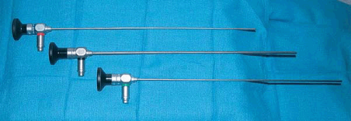 FIGURE 11.6 Hysteroscopic telescopes offer a variety of views: top, the 30-degree objective; middle, the 9-degree objective; bottom, the 0-degree objective lens. |
Operative sheaths come in several varieties depending on the manufacturer and range between 7 and 8 mm OD (Figs. 11.12, 11.13A, B). The most common design consists of a hollow tube, usually fitted with two stopcocks (right and left) for the installation of the distending medium. An operating channel mounted on the posterior or anterior surface and fitted with a stopcock feeds into the common channel. Opposite the operative channel is an interior groove where the telescope is seated. Since the distending medium is injected into a common channel (i.e., both instilling channels open into the same space), it is not feasible to flush the uterine cavity by injecting through one channel while leaving the opposite stopcock open. The operating channel must be fitted with a rubber nipple (gasket) to prevent the loss of medium and distention when operating instruments are introduced. One problem with this system is the tendency for the gaskets to slip off and/or leak when traction or torque is applied to the operating instrument (Fig. 11.14, Table 11.1).
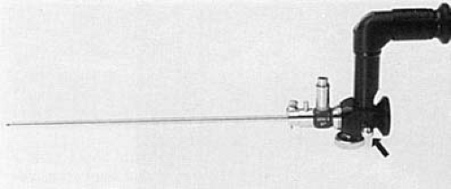 FIGURE 11.7 Button (arrow) on microhysteroscope allows switching to a lens system that magnifies up to ×150. |
A specialized sheath may be fitted with a terminal deflector or bridge that can be operated with two small wheels located just distal to the point where the sheath and telescope join (Fig. 11.15). These special sheaths usually are
constructed with an interposing bridge to allow selection with or without the deflector mechanism. The deflector may be used to angulate flexible instruments or fibers to one side by manipulating the wheel mechanism.
constructed with an interposing bridge to allow selection with or without the deflector mechanism. The deflector may be used to angulate flexible instruments or fibers to one side by manipulating the wheel mechanism.
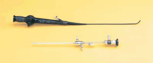 FIGURE 11.8 Top: A 3.2-mm flexible endoscope. Bottom: A rigid 3-mm telescope fitted to a 4-mm sheath. |
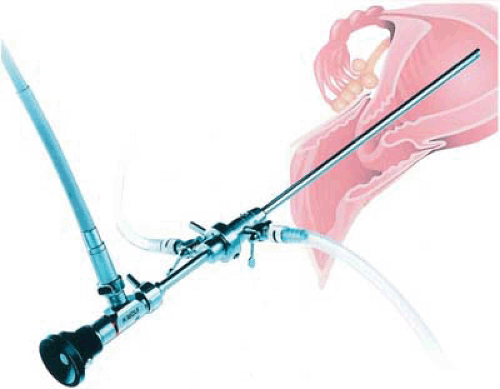 FIGURE 11.9 The telescope and sheath are joined and locked together. The fiberoptic cable is attached, and the distending medium flows through the 5-mm sheath. |
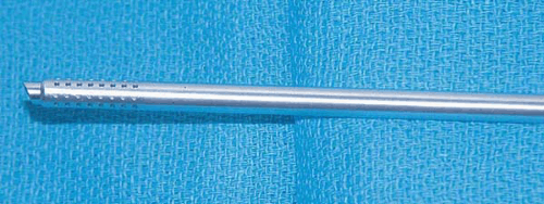 FIGURE 11.10 Tip of continuous-flow 5-mm sheath. The inner sheath dispenses the distending medium to the uterine cavity; the outer perforated sheath removes the tinged fluid from the cavity. This is also called a constant flushing sheath. |
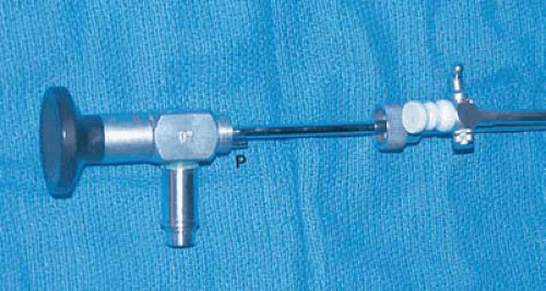 FIGURE 11.11 The telescope has been pulled back to demonstrate the coupling mechanism for this system. The correct junction between telescope and sheath is easily found by orienting the pin (P), which couples to a matching orifice in the sheath. The coupling is made watertight by screwing down the crown fitting of the sheath onto the threaded housing on the telescope. This is akin to the waterproof crown of a Rolex watch. |
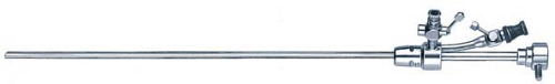 FIGURE 11.12 An operating hysteroscopic sheath. Note the channel through which instruments may be inserted. The nipple limits leakage of the distending medium. |
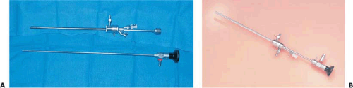 FIGURE 11.13 A: The operating sheath (top). Note the terminal portion of the sheath is beveled to accommodate the 30-degree telescope (bottom). B: The 30-degree telescope is coupled to the continuously irrigating operative sheath. |
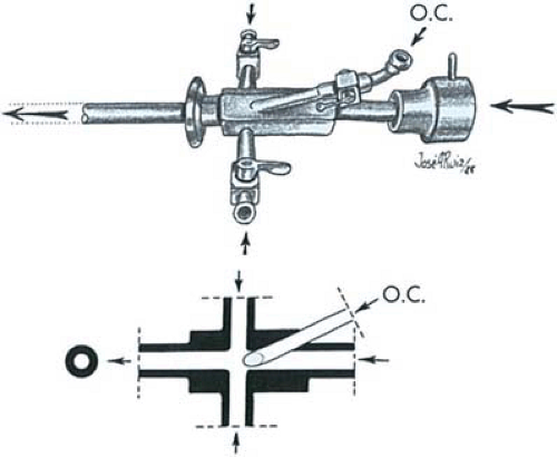 FIGURE 11.14 An operating sheath with two stopcocks. The operating channel (O.C.) feeds into a common channel (arrow). A rubber nipple prevents the loss of distending medium when an operating device is inserted. |
TABLE 11.1 Operative Hysteroscopes: Pertinent Features | ||||||||||||||||||||||||||||||||||||||||||||||||||||||||||||||||||||||||||||||||||||||||||||||||||||||||||||||||||||||||||||||||||||||||||||||||
|---|---|---|---|---|---|---|---|---|---|---|---|---|---|---|---|---|---|---|---|---|---|---|---|---|---|---|---|---|---|---|---|---|---|---|---|---|---|---|---|---|---|---|---|---|---|---|---|---|---|---|---|---|---|---|---|---|---|---|---|---|---|---|---|---|---|---|---|---|---|---|---|---|---|---|---|---|---|---|---|---|---|---|---|---|---|---|---|---|---|---|---|---|---|---|---|---|---|---|---|---|---|---|---|---|---|---|---|---|---|---|---|---|---|---|---|---|---|---|---|---|---|---|---|---|---|---|---|---|---|---|---|---|---|---|---|---|---|---|---|---|---|---|---|---|
| ||||||||||||||||||||||||||||||||||||||||||||||||||||||||||||||||||||||||||||||||||||||||||||||||||||||||||||||||||||||||||||||||||||||||||||||||
A contemporary design for an operating sheath provides isolated channels for the telescope and medium installation and incorporates an over-sheath for medium return (i.e., a true flushing hysteroscope). With this system, the uterine cavity can be flushed clear of debris. Additionally, the surgeon may operate and aspirate independently using a 6- or 9-French (2 or 3 mm) aspirating cannula (Fig. 11.16).
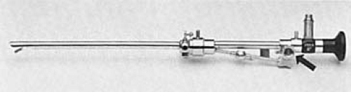 FIGURE 11.15 Special operating sheath equipped with a terminal deflector (bridge), which is controlled by a wheel mechanism (arrow). |
Most modern continuous-flow systems, however, have resolved the problem of using the same channels for inflow and outflow by isolating them and provide excellent washing of the uterine cavity. The gold standard for a 21st-century operative hysteroscopic sheath is a continuously flushing mechanism. This system uses an inner sheath to deliver fresh fluid into the uterine cavity and an outer perforated drain sheath to evacuate cloudy or discolored fluid from the cavity (Fig. 11.17A–D).
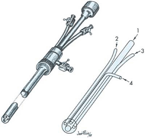 FIGURE 11.16 Dual operating channel sheath permits aspiration and operating at the same time. The sheath consists of four isolated channels: telescope (1); operating (2); operating (3); medium instillation (4). |
A variation of operative hysteroscopes has an offset right angle extension for the ocular, while the operative channels remain affixed to the straight portion of the endoscope. This
feature allows for the introduction of rigid instruments of larger outer diameter and sturdier makeup. Nonetheless, these hysteroscopes have not gained much popularity, particularly after the introduction of semirigid instruments for operative hysteroscopy delivered through the standard hysteroscopes.
feature allows for the introduction of rigid instruments of larger outer diameter and sturdier makeup. Nonetheless, these hysteroscopes have not gained much popularity, particularly after the introduction of semirigid instruments for operative hysteroscopy delivered through the standard hysteroscopes.
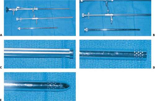 FIGURE 11.17 A: An isolated channel, continuous flushing, operative sheath (top). The outer drain-sheath has been removed to expose the inner sheath, which consists of isolated channels (middle). At the bottom is an introductory obturator attached to the outer drain sheath. B: This detail of the middle view in A shows the inner sheath. The stopcocks, which rotate, are labeled “inflow” and “outflow” for user ease. The separate, isolated channels accommodate the telescope, inflow fluid, and one or two operative tools. C: Magnified view of the terminal portion of an isolated channel inner sheath. D: Magnified view of the terminal portion of the isolated channel sheath shown in the top portion of A. The drain or outer sheath is multiply perforated, which allows it to continuously suck out cloudy fluid from within the uterine cavity. E: To facilitate easier entry of the 8-mm sheath through the cervix, the outer sheath serves as a conduit for an obturator, which is essentially a cloned dilator. |
The outer sheath can be inserted into the uterus with an obturator in a manner similar to a 26-French dilator (Fig. 11.17E). Next, the inner sheath fitted with the telescope is inserted and connected by a screw lock to the outer sheath. A copious 3-mm operating channel permits the use of sturdier, larger instruments including conventional tools, electrodes, and aspirating and suctioning devices (Fig. 11.18).
The Resectoscope
The urologic resectoscope has been used for decades to treat urinary bladder conditions and particularly for the resection of prostatic enlargement. The instrument has been modified for gynecologic use to remove submucous leiomyomas and endometrial polyps, for resection of uterine septa, for division of thick connective tissue adhesions, and for ablation of the endometrium to treat abnormal bleeding.
The resectoscope may be used with straightforward (0 degree), slightly fore-oblique (9-degree to 12-degree or 30-degree offset) telescopes. These telescopes range in diameter from 3 to 4 mm and can be encased in different sheaths of 7-, 8-, or 9-mm outer diameter (Fig. 11.19A, D). The instrument has a built-in system that provides motion by means of a spring that, when activated, moves the distal-fitted electrode forward and backward to shave, resect, or coagulate intrauterine lesions. The continuous-flow system is provided by two concentric sheaths, an outer sheath that provides the fluid outflow and an inner sheath that provides the inflow for continuous irrigation (Fig. 11.20A, B). Both concentric
sheaths assembled permit the introduction of an optical system for viewing, as well as the spring-loaded mechanism for manipulation of various electrodes. Because the cutting loop or coagulating electrodes can be manipulated directly and moved around several millimeters within the visual field of the objective lens, a clear unobstructed panoramic view of the lesion and the surrounding normal endometrium is essential to avoid accidental perforation (Fig. 11.20C). The instruments, manufactured by several companies, have similar features with minor modifications. The activation of the cutting loop or coagulating electrode is obtained by connection with a high-frequency electrosurgical unit; therefore, proper grounding of the patient is required. Furthermore, an electrolyte-free solution should be used for distension of the uterine cavity to avoid erratic condition and dispersion of monopolar electric current.
sheaths assembled permit the introduction of an optical system for viewing, as well as the spring-loaded mechanism for manipulation of various electrodes. Because the cutting loop or coagulating electrodes can be manipulated directly and moved around several millimeters within the visual field of the objective lens, a clear unobstructed panoramic view of the lesion and the surrounding normal endometrium is essential to avoid accidental perforation (Fig. 11.20C). The instruments, manufactured by several companies, have similar features with minor modifications. The activation of the cutting loop or coagulating electrode is obtained by connection with a high-frequency electrosurgical unit; therefore, proper grounding of the patient is required. Furthermore, an electrolyte-free solution should be used for distension of the uterine cavity to avoid erratic condition and dispersion of monopolar electric current.
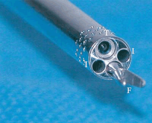 FIGURE 11.18 This end-on view of an operating sheath shows the telescope’s objective lens (T), liquid medium inflow channels (I), and a 3-mm gasping forceps (F) exiting the operating channel. |
Of late, a bipolar resectoscope has been introduced (Versapoint) that permits use of electrolyte-containing fluids during its operation. This instrument mimics the bipolar system by adapting the active and receptive electrodes in the same instrument (Fig. 11.21). Every gynecologic surgeon who chooses to use a resectoscope, or for that matter any operative tool, must know how the instrument works, how to assemble and disassemble the device, and how to insert and remove the electrode (Fig. 11.22).
A new instrument is being tested for resectoscopy that provides capabilities of resection and/or coagulation of intrauterine lesions, as well as simultaneous morcellation of resected tissue with continuous aspiration. The Opera Star System with disposable cannulas provides this capability. The only reusable portion of the system is the telescope with 0-degree to 12-degree direction of view. This system is being evaluated for resectoscopy and offers the advantage of removing tissues simultaneously with suction, thereby decreasing operative time and additional uterine manipulation for evacuation of the resected tissue. A clear field of view is maintained, and the intrauterine cavity is continuously emptied of resected tissue. Clinical evaluations of such prototypes are being conducted. No clinical acceptance and approval has occurred, nonetheless.
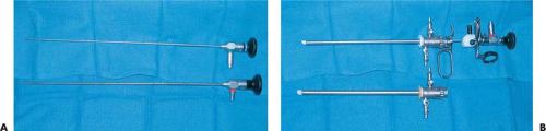 FIGURE 11.19 A: Two telescopes (0 degrees and 30 degrees), which may be inserted into the resectoscope sheath depending on the preference of the surgeon. For close-in work, the 30-degree offset scope is preferred. B: The 7-mm sheath above accepts a 3-mm OD telescope. Below, the standard 8- to 9-mm sheath accepts a 4-mm OD telescope. Both sheaths have continuous flushing capability. |
Light Sources
The quality and quantity of light delivered to the telescope depend equally on the type of the light generator and the transmitting fiberoptic cable. The simplest light generator provides only 150 W of power, which suffices for direct-view hysteroscopy when photography is not desired. These light sources may be purchased at a modest cost and because of their compact design are ideal for office hysteroscopy. More elaborate light sources are available that produce very high intensity light. The xenon generator provides 300 W of
intense power with a current meter readout from 7 to 21 amp and is recommended with video-control hysteroscopy as well as for photography (Fig. 11.23). The variable illumination settings and special filters provide tailor-made light for various situations. The metal-halide light sources produce a bluish coloration to the delivered light. Most of the less expensive tungsten-type sources dominate in the orange-red wavelengths. Regardless of the type of light generated, whatever reaches the telescope depends on the quality and maintenance of the fiberoptic light cable. Cables
should be handled gently. They cannot be dropped, banged about, or tightly wound up. Poor illumination is almost always related to damaged light cables. Generally, the liquid cables transmit the most effectively. The surgeon should regularly check fiberoptic cables in a dark room to look for broken fibers, which are detected by noting illuminated spots along the cladding. If the surgeon cannot see well, the problem requires immediate remedy or the surgery should be stopped (Fig. 11.24).
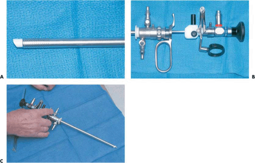 FIGURE 11.20 A: This magnified view provides detail about the resectoscopic sheath. The white shroud is nonconductive and provides insulation for the retracted double-armed electrode. Fluid inflow emits through this common channel. The perforated over-sheath provides an exit for the cloudy infusion medium. B: Detail of the trigger mechanism of this resectoscope. The surgeon’s thumb engages into the black ring nearest the telescope’s eyepiece. The index finger engages the trigger as the center finger and ring fingers are applied through the oblong steel ring. As the trigger is pulled toward the surgeon, the electrode is progressively extended out, away from the sheath. Relaxation on the spring-tensioned trigger, i.e., allowing the mechanism to retreat to its resting position, causes the electrode to return toward the sheath. C: As the trigger is relaxed and the tension on the handle released, the electrode is retracted. |
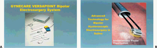 FIGURE 11.21 A: Bipolar system that uses innovative instrumentation. The neutral and active electrodes are components within the same instruments. B: Close-up of a bipolar resectoscope. |
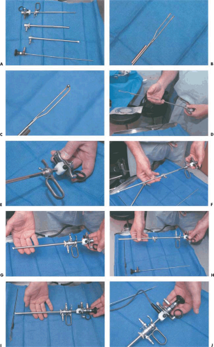 FIGURE 11.22 A: The resectoscope has been disassembled into its component parts. B: The curved, monopolar, dual-armed electrode is used for cutting tissue on the anterior or posterior uterine walls. C: The ball electrode is suited for coagulation and ablative procedures. D: The electrode is fed into the guidance system of the sheath. E: The proximal insulation-free conductor of the electrode is seated and locked into the electrosurgical housing. F: The under-sheath is now inserted over the electrode. This will bring fluid to the operative field. G: The inner sheath is now locked into place. H: The outer sheath is placed into position. I: The sheath and telescope are joined, and the resectoscope is ready for use. J: The electric cord is connected. |
Sterilization
The current standard for sterilization of endoscopes is gas sterilization with ethylene oxide. Some newer telescopes may be steam autoclaved (flash) on an emergency basis without damaging the lenses; however, this latter type of sterilization cannot be a routine.
With the expansion of endoscopic procedures in medicine, new methods for rapid and safe sterilization of instruments were introduced. Low-temperature sterile processing systems such as the Steris System 1 offer such assurance, and its microcomputer-controlled monitor was introduced and widely used. Using peroxyacetic acid (PAA) in a simple-to-use unit that permits quick and repetitive sterilization of the instruments, as required, provided an easy access for use. However, although using a short cycle controlled by a low-temperature unit facilitated sterilization of endoscopes, they could not be stored for a long period of time because no wrappings were used, since wrappings are unsuitable for most heat-sensitive devices; this made the maintenance of instrumentation somewhat difficult. A new generation of low-temperature sterilization systems, the STERRAD 100 and of late the STERRAD 50 sterilizers, developed by Advance Sterilization Products (ASP), a Johnson and Johnson Company, uses the combination of hydrogen peroxide vapor and low-temperature gas plasma to rapidly sterilize medical instruments in minutes; these systems require no aeration, avoid leaving toxic residue, and produce no emissions. Sterilization using the STERRAD 50 destroys a broad spectrum of micro-organisms and is compatible with most surgical instruments. Therefore, it lowers sterilization operating costs by reducing damage to instruments and reduces costs for repair of expensive and delicate instruments.
The new generation disinfectants are the Cidex OPA (0.55% ortho-phthalaldehyde [OPA]) solutions that have
practically replaced the glutaraldehyde, making the process of sterilization more rapid, a 12-minute soak time at 20°C or 5-minute soak time at the minimum of 25°C in an automatic endoscope reprocessor (AER), making this solution more appealing for use. Furthermore, it enhances safety and reduces instrument damage. Testing of the solution has demonstrated its efficacy as bactericidal, including spores, fungicidal, tuberculocidal, as well as virucidal. However, although the time of soaking is decreased, it requires three 1-minute rinses to remove residual Cidex OPA solution before use.
practically replaced the glutaraldehyde, making the process of sterilization more rapid, a 12-minute soak time at 20°C or 5-minute soak time at the minimum of 25°C in an automatic endoscope reprocessor (AER), making this solution more appealing for use. Furthermore, it enhances safety and reduces instrument damage. Testing of the solution has demonstrated its efficacy as bactericidal, including spores, fungicidal, tuberculocidal, as well as virucidal. However, although the time of soaking is decreased, it requires three 1-minute rinses to remove residual Cidex OPA solution before use.
Related posts:


Stay updated, free articles. Join our Telegram channel

Full access? Get Clinical Tree


