Optical Principles of the Endoscope
Jakob Kopp
Fred M. Gardner
An endoscope is an optical system that enables the viewer to recognize information from parts of an object that are not directly accessible. Endoscopes are used as much in medical fields as in technical fields. Various endoscopes, such as arthroscopes, bronchoscopes, laryngoscopes, laparoscopes, gastroscopes, and hysteroscopes, have been devised to serve the needs of physicians within the medical specialties. Technical applications include the control and inspection of processes in engines, turbine drives, aircraft production, and welding. However, the optical principles and the basic features used in these different instruments are similar. Viewed from the outside these various scopes differ mainly in diameter and length.
Basically, an endoscope consists of an optical system to carry light to illuminate the object being viewed and either the same (as in the contact hysteroscope) or a different optical mechanism for conveying the image back to the eye or camera. The image may be conveyed through a series of lenses, in which case the endoscope tube is rigid, or it may be carried to the viewer by means of light trapped in a flexible fiberoptic bundle. In most modern endoscopes, the illuminating light is carried to the object by an optical fiber bundle. In addition to illuminating and image capabilities, most endoscopes have channels that allow the passage of biopsy forceps, gas, liquids, laser radiation, and various surgical tools. Generally, endoscopes may be divided into flexible and rigid categories.
Fiberoptic Principles
The transmission of light through a glass fiber depends on the phenomenon of total internal reflection. If a fiber is straight or curved, light entering one end travels in a zigzag path, repeatedly reflecting off the internal surface of the fiber, until it emerges from the other end. The transmission of visible light (0.40 μm to 0.70 μm) through fibers having diameters of 8 μm or more can be traced by the application of the principles of geometric optics. In fibers smaller than 8 μm, diffraction losses occur, significantly reducing the intensity of the transmitted light. For this reason, endoscopes use fibers with diameters of approximately 10 μm. A single fiber consists of a core and a cladding (Fig. 9.1).
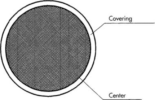 FIGURE 9.1 A single optical fiber consisting of a central core and a cladding. |
Refraction of a Light Ray
When light is incident from air onto a transparent medium such as glass, part of the light intensity is reflected back into the air and part is transmitted into the glass (Fig. 9.2). For the reflected component, the incident angle θi equals the reflected angle θi′ The transmitted ray, however, changes direction at the interface because of the difference of the speed of light in air and in glass. Because the speed of the ray slows down as it passes from the air into the glass, the ray bends toward the interface normal, and θi > θr. The amount of bending or refraction in passing from air into glass can be given as the index of refraction of the glass relative to air. This is defined as the ratio of the speed of light in air (a) to the speed of light in the glass (g); n = va/vg. Usually the index of refraction of a transparent medium is given relative to the speed of light in a vacuum (c = 3.0 × 10⁸ m/sec); that is, n = c/v. Typical optical glasses have refractive indices between 1.5 and 1.7 for the visible spectrum.
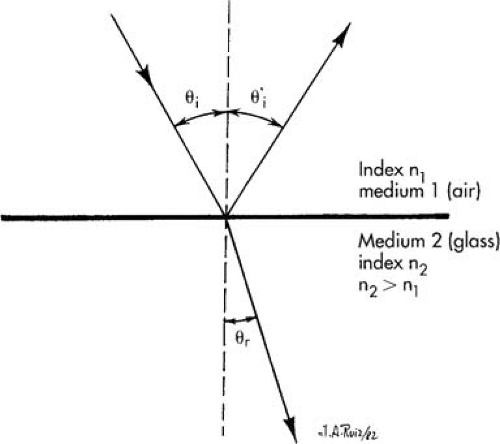 FIGURE 9.2 Reflection and refraction of light at an interface between two transparent media. |
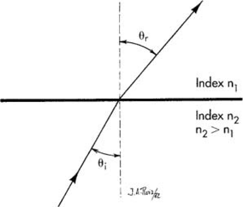 FIGURE 9.3 A ray incident on an interface from the higher index side bends away from the interface normal. |
The relationship between θi and θr is given by Snell’s law:
Total Internal Reflection
If a ray travels from a higher refractive index medium to a lower index medium (Fig. 9.3), Snell’s law predicts that the ray will bend away from the interface normal; that is, θi < θr. As the incident angle is increased, the angle of refraction becomes larger until it finally reaches 90 degrees. The angle of incidence for which the angle of refraction is 90 degrees is called the critical angle. The critical angle has a value between 36 degrees and 42 degrees for typical optical glasses in air. At the critical angle, the ray exists parallel to the refractive surface.
If the critical angle is exceeded, the ray reflects from the interface back into the higher index medium. This internal reflection is nearly total if the surface is microscopically smooth. The critical angle and total internal reflection are illustrated in Figure 9.4.
If a ray or light enters one end of a glass fiber in air at an angle such that the critical angle is exceeded at the cylindrical surface, the ray will be transmitted to the other end by a series of internal reflections (Fig. 9.5). In a typical 10-μm diameter fiber, a ray reflects many thousands of times in traveling in a 1-m distance. The reflection is similar to that occurring from a mirror. Hence, it is necessary that the reflections be nearly perfect. If the surface of the fiber is not microscopically perfect or if any contaminant lies on the surface, the reflection coefficient will not be 100%, and some light will escape. For this reason, the transmitting fibers are clad with a lower index glass (Fig. 9.5). The coaxial fiber is produced by being drawn through a furnace so that the cladding is optically fused to the core.
Cladding the fiber changes the critical angle for total reflection from sin θc = 1.00/n1. When the core is in air, the angle changes to sin θc = n2/n1 for the cladded case. Here n2 is the refractive index of the cladding and n1 is the refractive index of the core. Bending of the fiber or the fiber bundle affects only the angle of total reflection. The principle of ray tracing remains. A single fiber for imaging is about 10 μm in diameter. This affects the resolution of images. Such a coherent fiber bundle transmits 50 L/mm maximum.
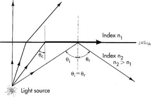 FIGURE 9.4 Ray diagram showing the critical angle and total internal reflection. |
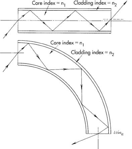 FIGURE 9.5 Transmission of a light ray through a flexible fiber by total internal reflection. |
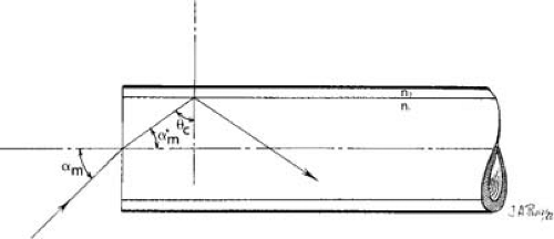 FIGURE 9.6 Ray entering a straight fiber at an angle σm for which the incident angle on the fiber wall is θc. |
Numerical Aperture of a Fiber
Figure 9.6 shows a ray entering the end of a straight, cylindrical fiber core with an index of n1 clad with a medium of index n2, where n1 > n2. The ray is incident from a medium of index n0 at an angle α to the fiber axis. The ray will be refracted at the end face of the fiber and will be totally reflected at the cylindrical fiber wall if the incident angle at the fiber wall is greater than the critical angle θc. The maximum value of the incident angle, αm, for which the ray will be totally reflected at the fiber wall can be calculated using Snell’s law: n0 sin σm = n1 sin αm′ = n1 cos θc = n1 (1 – sin2θc)1/2, sin θc = n2 /n1. Hence, n0 sin σm (n12 − n21)1/2.
The numerical aperture (NA) of the fiber is defined as n0 sin σm. Hence, NA (n12 − n22)1/2. The numerical aperture is a measure of the light-gathering power of the fiber. A typical fiber core having a refractive index of m1 = 1.62 and a typical cladding having a refractive index of n2 = 1.52 would produce a numerical aperture of 0.56. If the ray is entering the fiber from an air medium, n0 = 1.00, and the acceptance half-angle is 34 degrees. Hence, the acceptance cone angle is 68 degrees. If the ray enters from water, n0 = 1.33, and the acceptance cone angle is 50 degrees.
In practice, several factors combine to produce an NA and an acceptance angle smaller than defined here. Attempts to increase the NA by increasing n1, the refractive index of the core, will lead to a lower transmittance of the blue end of the visible spectrum. However, the selective transmittance is usually not a problem except for very long fibers or when ultraviolet light is being used for illumination.
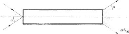 FIGURE 9.7 Any distribution of light within the acceptance cone at the entry face of a fiber will be uniformly distributed over the exit face of the fiber. |
Coherent Fiber Bundles
To transmit an optical image through a bundle of fibers, the fibers must have the same relative arrangement at the distal end as at the proximal end. Fiber bundles of this type are said to be coherent.
Light originating from an object and entering the distal end of a fiber, after many internal reflections, emerges uniformly distributed over the exit face of the fiber (Fig. 9.7). Any detailed distribution of light over a single fiber is lost after transmission through the fiber. This blurring of the
light distribution by transmission through the fiber sets a limit to the ability of fiber bundles to resolve fine detail. For the case when the fiber bundle is stationary with respect to the object, the smallest detail of the light distribution on the distal face that can be resolved at the proximal end is approximately 2.5 d, where d is the diameter of a fiber.
light distribution by transmission through the fiber sets a limit to the ability of fiber bundles to resolve fine detail. For the case when the fiber bundle is stationary with respect to the object, the smallest detail of the light distribution on the distal face that can be resolved at the proximal end is approximately 2.5 d, where d is the diameter of a fiber.
To produce images for viewing, the fiberoptic coherent bundle makes use of an objective lens system and an eyepiece (Fig. 9.8). The objective lens system focuses a real image of the object being viewed onto the distal fiber bundle face. The coherent bundle transmits this image to the proximal end face. Here the eyepiece views the transmitted image and forms a magnified virtual image at a distance of approximately 25 cm in front of the normal eye. The magnification of the eyepiece has to fit to the fiber bundle because the structure of the bundle is visible and should not be determined by the visible image quality.
The overall magnification of the endoscope is given by the product of the magnification of the objective lens and the eyepiece. The eyepiece magnification is usually limited to ×10 because of the discrete nature of the fiber bundle. The magnification of the objective lens is <1 and is inversely proportional to the distance between the object and the lens. Hence, an exact magnification for a fiberoptic endoscope can be given only if the object distance is known.
In practice, objects to be viewed are located at different distances from the objective lens. Either some means of focusing must be built into the objective lens system or sufficient depth of focus must be provided. For medical endoscopes, the latter approach is usually taken, since distal focusing presents mechanical as well as sterilizing difficulties.
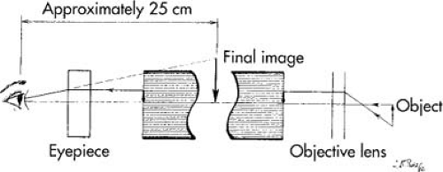 FIGURE 9.8 Schematic of fiberoptic endoscope showing the object and image positions. |
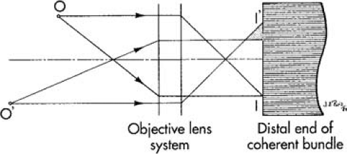 FIGURE 9.9 The objective lens system focuses a sharp image of a source of light at O on the fiber face at I. Another object at O′, which is farther from the objective lens than O, produces an out-of-focus image I′ on the fiber face. |
Light focused on the distal fiber face is transmitted to the proximal end. If the distal image is poorly focused, the image on the proximal face will be of poor quality, and no refocusing of the eyepiece can bring the image to sharp focus. Figure 9.9 shows the schematic of an objective lens system and distal end of the coherent fiber bundle set to produce a sharp focus on the fiber face of an object located at O. An object at O′ will produce an out-of-focus patch of light covering a number of fibers, resulting in a loss of image quality.
Related posts:


Stay updated, free articles. Join our Telegram channel

Full access? Get Clinical Tree


