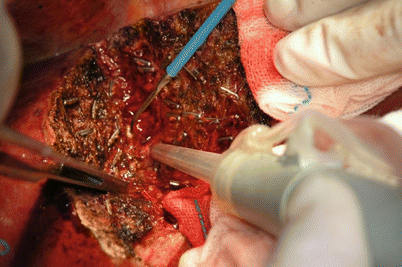
Fig. 29.1
Shows the donor’s incision
29.4.2 Exploration and Mobilization of the Donor Liver
The normal liver is bright red and sharp edged (see Fig. 29.2). A few liver tissue samples are typically taken for intraoperative biopsy.
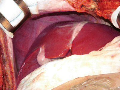

Fig. 29.2
Shows the normal donor’s liver
29.4.3 Dissection of the First Porta Hepatis
29.4.3.1 Intraoperative Cholangiography
The gallbladder is excised, and then, intraoperative cholangiography is conducted through the cystic duct with clamping of the common bile duct with a biliary clip at the superior border of the duodenum to explore the intrahepatic bile ducts (see Figs. 29.3 and 29.4). A titanium clip is used to clamp the hilar plate tissue at the junction of the common hepatic and right hepatic ducts. The confluence of right hepatic bile duct is located, and the resection line at hilar plate is marked (see Fig. 29.5).
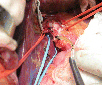
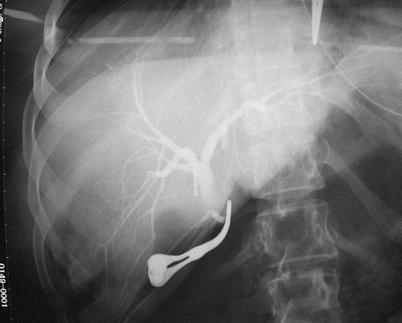
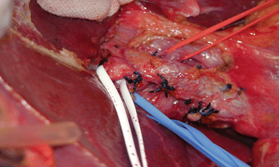

Fig. 29.3
Shows intraoperative cholangiography by intubation of cystic duct

Fig. 29.4
Shows the titanium clip located at the junction of the common hepatic and right hepatic ducts

Fig. 29.5
Shows the structures of the first porta hepatis (right hepatic artery with red sling, right hepatic duct with white sling, and the right portal vein with blue sling)
29.4.3.2 Separation and Dissection of Vessels and Ducts
Dissections must be performed carefully to avoid electrocoagulation and additional injuries and to prevent the capillary network from supplying the bile ducts. The right hepatic artery and right portal vein are dissected. If the right hepatic ducts are converged by 2–3 hepatic bile ducts, they are typically transected with the right hilar plate at the same time after splitting the liver parenchyma rather than dissecting it at the beginning.
There may be variations of the portal vein, as four types often occur (see Fig. 29.6). Types I and II are suitable for LDLT. However, types III and IV are difficult for bile duct reconstruction [8].
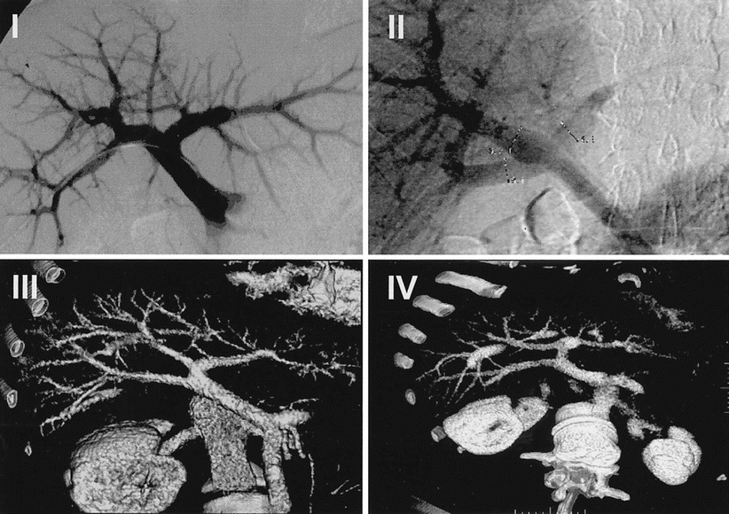

Fig. 29.6
Shows the four types of portal vein
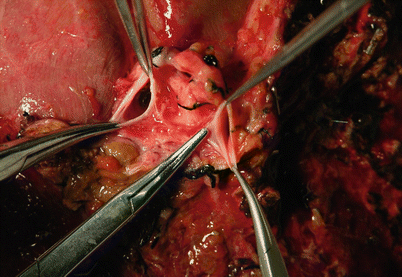
The figures below show the preoperative CT imaging and intraoperative finding of a donor with type II portal vein (Figs. 29.7 and 29.8, 29.9, 29.10, and 29.11).
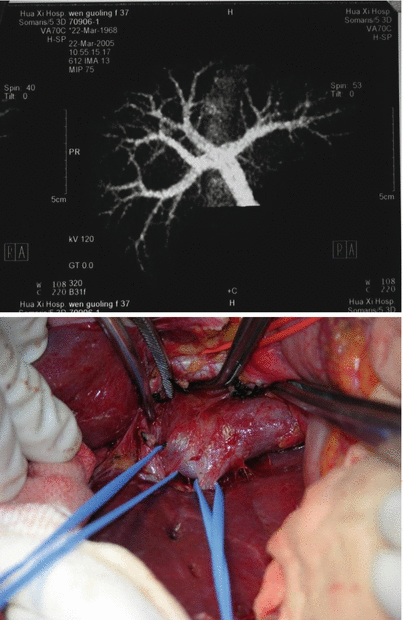

Figs. 29.7 and 29.8
Show preoperative CT imaging and the intraoperative finding of the right portal vein with right anterior and right posterior branches

Fig. 29.9
Shows openings at the right anterior and right posterior branches of the type II portal vein

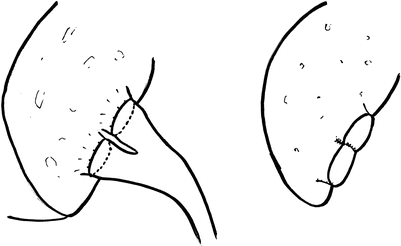
Fig. 29.10
Shows two types of reconstructions of the type II right portal vein with right anterior and right posterior branches. The left picture shows an anastomosis of the recipient’s left and right portal veins with the donor’s two right portal vein branches. The right picture shows reshaping of the donor’s two right portal vein branches as a common opening to anastomosis with the recipient’s main portal vein when the two branches are adjacent

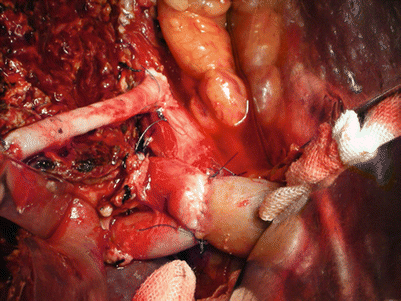
Fig. 29.11
Shows that the author used a cadaveric iliac U-shaped artery to reconstruct and form an anastomosis with the recipient’s portal vein
29.4.4 Separation of Perihepatic Ligaments
The hepatocolic ligament, right triangular ligament, and right coronary ligament are successively resected, exposing the right adrenal gland and right margin of the posthepatic inferior vena cava (IVC).
29.4.5 Dissection and Transection of the Third Porta Hepatis and Right Hepatic Vein
The assistant helps push the liver to the left without force. All of the short hepatic veins on the right side of the posthepatic IVC are transected. If the short hepatic vein or accessory right hepatic vein is more than 0.5 cm in diameter, it should be preserved and reconstructed (Fig. 29.12).
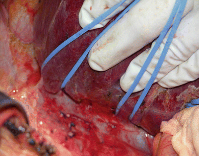

Fig. 29.12
Shows the right hepatic vein with the left sling and the large inferior right hepatic vein for reconstruction with the right sling
The right liver is intermittently lifted to avoid compressing and occluding hepatic inflow that might result in liver injury when handling the short hepatic veins.
29.4.6 Transection of the Liver Parenchyma
29.4.6.1 Prediction of the Resection Line of the Right Hemiliver Excluding the MHV by 3-D Reconstructive CT (Figs. 29.13 and 29.14, 29.15 and 29.16)
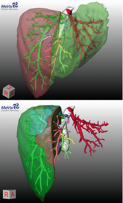
Figs. 29.13 and 29.14
Show the 3-D images of the donor’s whole and right liver, respectively
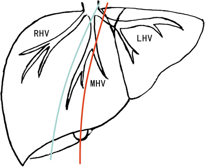
Fig. 29.15
Shows the predictive resection line of the right hemiliver including and excluding the MHV. LHV: Left hepatic vein; RHV: Right hepatic vein
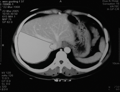
Fig. 29.16
Shows the right hemiliver excluding the MHV during CT imaging
The resection line is conformed intraoperatively in three ways: (1) the ischemia line of the left and right livers is used by temporarily occluding the right hepatic blood inflow as the resection line, (2) the Cantlie line (which is the connecting line at the liver surface stretching from the middle of the gallbladder fossa to the midpoint of the right and MHVs at the second porta hepatis) is used, and (3) the intraoperative ultrasound is used to confirm the resection line (Figs. 29.17, 29.18, and 29.19).
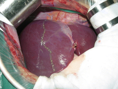
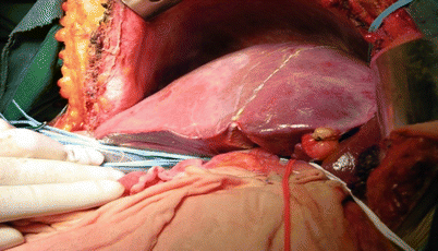
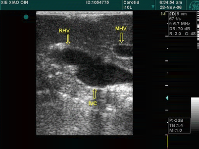

Fig. 29.17
Shows the donor ischemia line

Fig. 29.18
Shows the Cantlie line at the surface of the liver

Fig. 29.19
Shows the intraoperative ultrasound confirming the resection line
29.4.6.2 Transection of the Liver Parenchyma
The liver capsule is cut with an electrotome along the resection line, and the cavitron ultrasonic surgical aspirator (CUSA) is used to skeletonize the intrahepatic vessels. The assistant uses the bipolar coagulator or electrotome to coagulate the bleeding points at the liver cross-section and to expose the operation field by using scissors to compress the liver cross-section. The vessels at the liver section less than 3 mm in diameter are resected after clamping with a titanium clip, vessels between 3 and 5 mm in diameter are cut off after ligation, and vessels more than 5 mm in diameter should be preserved and reconstructed. A rubber sling is placed between the back of the liver and the front of the IVC through the left side of the right hepatic vein and the internal side of the portal bifurcation. The sling can pull the liver up when transecting the liver tissue adhering in front of the IVC to prevent the IVC from unexpected surgical injuries and to increase surgical field exposure (Fig. 29.20).

