Fig. 16.1
(a, b) Siemens Magnetom MRI (low-field (0.2-T) biplanar magnet design) (Courtesy of Siemens Healthcare 2014)
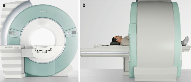
Fig. 16.2
(a, b). Siemens Magnetom Espree MRI (high-field (1.5-T) short-bore magnet design) (Courtesy of Siemens Healthcare 2014)
MR-guided ablation also requires the ability to operate the scanner and review images at the patient’s bedside. Most systems will come equipped with an in-room monitor with mouse or built-in trackball and foot pedal to allow for control of MR sequences from the scanner side, facilitating interactive near-real-time navigation of the ablation probes into the targeted tumor (Fig. 16.3).
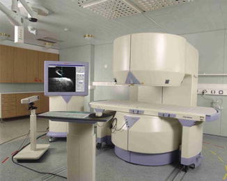
Fig. 16.3
Philips Medical Systems Open Configuration interventional MRI unit with in-room monitor, in-room workstation with imaging capability, and a foot pedal for the operator which controlled sequence start
An MRI-compatible ablation system is also necessary. Meaning MRI-compatible electrodes for RFA and cryoprobes for CA need to be utilized. MRI-compatible systems are available for both RFA and CA and are discussed in more detail below.
In addition, MRI-compatible anesthesia equipment and monitoring devices are integral parts of the MRI-guided renal ablation and are typically already available in most diagnostic MRI suites.
Patient Selection
It is important to emphasize that the recommended treatment and standard of care for the management of clinical T1a renal cell carcinoma is nephron-sparing surgical extirpation [12]. However, partial nephrectomy remains associated with significant morbidity and is not always feasible or suitable. Alternatively, image-guided percutaneous ablation represents a less invasive treatment option with reduced morbidity ideally suited for patients of advanced age or with major comorbidities and increased surgical risk who prefer a proactive approach but are not optimal candidates for conventional surgery. Thermal ablation also represents a good treatment option in patients with solitary kidney, renal insufficiency, bilateral tumors, local recurrence after previous nephron-sparing surgery, and patients with a genetic predisposition for developing multiple tumors (e.g., VHL syndrome) [29]. The American Urological Association guidelines on the management of small renal masses recommend thermal ablation as a treatment option for patients with major comorbidities or increased surgical risk who want active treatment [12]. The European Association of Urology guidelines on RCC recommend thermal ablation for patients with small tumors and/or significant comorbidity who are unfit for surgery [30].
Tumor size also represents an important factor in patient selection. Current technology does not allow for reliable treatment of lesions larger than 4.0 cm in diameter [31]. The evidence in the literature suggests that smaller tumors are more effectively ablated than larger ones. In one retrospective series using RFA in 100 renal tumors, complete ablation was achieved in 100 % of tumors smaller than 3 cm, 92 % of tumors between 3 and 5 cm, and 25 % of tumors larger than 5 cm [32]. Similarly, another study showed that with each 1-cm increase in tumor diameter over 3.6 cm, the likelihood of recurrence-free survival decreased by a factor of 2.19 [33]. In our experience, the optimal tumor size for percutaneous thermal ablation is ≤3 cm as higher local recurrence rates and complication rates occur with tumors larger than this.
Contraindications to percutaneous ablative therapy include poor life expectancy of <1 year, multiple metastases, low possibility of successful treatment due to size or location of tumor, irreversible coagulopathy, inability to lie supine or prone for prolonged periods because of pulmonary compromise, or other medical comorbidities [20, 30].
Patient Position
Patients are placed in a position that allows the shortest and least complicated access to the tumor. The prone or lateral decubitus positions are most commonly used. Unfortunately, there are no studies comparing the efficacy of these different positions.
Prone
The prone position is advantageous because it is a stable position that is usually comfortable for the patient and it also typically allows a short targeting distance, especially to lower pole renal masses. If the prone position is used, it is helpful to place a pillow under the abdomen of the patient to separate the costal margin and iliac crest, to provide a larger window for probe placement.
Of note, most patients’ pre-procedure imaging is performed in the supine position, and a recent study performed at our institution revealed some clinically important anatomic alternations associated with change from the supine to the prone position [34]. Specifically, in the prone position, the kidneys are more anterior and more cranially located, with an associated significantly shorter skin to tumor distance. In addition, the colon is closer to the kidney and more posteriorly located on both sides. Lastly, on the right side, more of the kidney is covered posteriorly by the lung. Accordingly, the prone position may limit access, particularly for right upper pole tumors.
Lateral Decubitus
Conversely, the lateral decubitus position also provides some distinct advantages. Either the ipsilateral or contralateral side may be placed on the downside depending on the situation. When the ipsilateral side is placed down, the kidney moves less with respiration, and there is less chance of a pneumothorax because the ipsilateral lung is deflated relative to the other side. This position is particularly helpful when targeting upper pole tumors that require an intercostal approach [20]. When the contralateral side is placed down, the bowels fall medially and away from the kidney making it useful for treating anterior lesions close to the bowel [20]. Additionally, this position provides a greater working area, which can allow for easier access to the lesion.
Safety Issues
When performing MRI-guided ablation, one has to be acutely aware of the magnetic field. Although risks and safety issues are less prominent with low and medium field-strength (0.2–0.5-T) magnets, which are typically used for MR-guided renal ablation, hazardous consequences can result nonetheless when ferromagnetic instruments become accelerated in the fringe field of the scanner. To avoid serious or even fatal injuries, no ferromagnetic materials should be brought within the 5-G line of any scanner. Additionally, all scalpels, needles, RF electrodes or cryoprobes, and anesthesia equipment should be made of MRI-compatible materials. Similarly, physiologic monitors should be non-ferromagnetic or should be kept outside the fringe field of the magnet.
Electric burns can also be a concern and typically result from direct electromagnetic induction in a conductive loop, induction in a resonant conducting loop, or electric field resonant coupling with a wire [35–37]. Limiting conductive loops, wire–patient contact, and cable lengths can minimize the risk of electric burns [20].
Ablation Modality
As mentioned previously, a number of ablation modalities exist; however, the most widely clinically applied and most thoroughly investigated are RFA [32, 38–41] and CA [42–45]. The choice of ablative modality is based on numerous factors but is largely dependent on equipment availability and the experience and preference of the urologist/interventional radiologist. Also of key importance with MR-guided ablation is an MRI-compatible ablation system.
Radiofrequency Ablation
RFA works by delivering radiofrequency current (375–500 kHz) into target tissue through an electrode connected to a radiofrequency generator. Tissue impedance from the radiofrequency current causes ionic agitation of intracellular molecules, resulting in frictional heating [19, 46]. At 60 °C there is denaturation of structural proteins and near instantaneous coagulative necrosis of tissue [20].
MR-compatible electrodes have been made available by at least two manufacturers. These are the titanium electrodes of the Cool-tip™ RF system (Covidien, Boulder, CO, USA) and the nitinol electrodes of the StarBurst Semi-Flex™ from the AngioDynamics system (AngioDynamics, Queensbury, NY, USA).
The Cool-tip™ RF system provides electrodes that can be continuously cooled with circulating iced water inside the electrode shaft that is meant to reduce charring at the electrode–tissue interface, thereby maximizing the ablation size.
The StarBurst Semi-Flex™ RF electrode provides electrodes with multiple active tines that can be deployed in the target tissue to produce larger ablation zones, in addition to a flexible shaft that can be bent to improve the capability for electrode navigation in the rather tight space usually available during interventional MRI procedures.
A number of reports of successful treatment of RCN with CT-guided percutaneous RFA have been published. However, CT guidance does not allow for real-time monitoring of RFA, as the thermal ablation zone is not visible. Conversely, RFA can be monitored in real time with MRI [24, 25] but is limited by the need to interrupt the radiofrequency energy during MR imaging due to significant interference it causes otherwise.
Cryoablation
CA works by freezing tissue to below −30° to −40 °C, which subsequently results in direct cellular damage and cell death due to cellular dehydration and cell membrane rupture [47]. Additionally, there is indirect reperfusion injury during the thawing phase that results in microcirculatory failure and small vessel thrombosis.
Currently, only one MR-compatible CA system is available. The MRI SeedNet® System (Galil Medical, Yokneam, Israel) is a stand-alone CA system, compatible with all MRI systems (closed or open bore) up to 1.5 T (Fig. 16.4a). The SeedNet® MRI mobile unit is placed within the MRI room, allowing the treating physician access to both the patient and the needles during the CA treatment. A full range of small-diameter MRI-compatible CA needles are available (Fig. 16.4b).
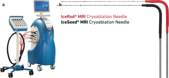
Fig. 16.4
(a) MRI-compatible Galil SeedNet® Cryoablation System. (b) Galil MRI-compatible IceSeed® 1.5 MRI Cryoablation Needle and IceRod® 1.5 MRI Cryoablation Needle (Used with permission. ©2013 Galil Medical)
Several reports have been published demonstrating the safety and efficacy of CT-guided percutaneous CA of RCN [44, 48, 49]. Although the ice ball is readily apparent as hypoattenuating lesion in the renal parenchyma on CT guidance, there are a couple of limitations to monitoring the zone of CA with CT. First, the portion of the ice ball in the perinephric fat is not clearly demarcated, which limits its use for real-time monitoring of the effect of ablation on adjacent critical structures such as bowel, ureter, pancreas, and adrenal gland [50–52]. Second, the streak artifact created by the cryoprobes with CT imaging can interfere with ice ball visibility [28].
Conversely, MRI depicts the ice ball with sharp edge definition in multiple planes in all surrounding tissue and with minimal applicator artifact. In addition, ice ball volume on intra-procedural MRI has been shown to correlate well with volume of cryonecrosis on post-procedural MRI. Furthermore, the ice ball is well depicted on all pulse sequences, so the ablation can be monitored using pulse sequences that best display tumor or adjacent critical structures [53].
Procedure Guidance and Treatment Monitoring
Once the patient is appropriately positioned and sedation or general anesthesia is administered, axial fast spin-echo images are obtained to localize the kidneys and target the mass. These images are also used to plan probe entry site and trajectory. The skin entry point may be located using a fingertip, syringe filled with water for T2-weighted image guidance, or with dilute gadolinium for a T1-weighted approach [54].
Next, the skin site is marked and prepared and draped in sterile fashion. After anesthetizing the skin with 1 % lidocaine with epinephrine, a 2–3 mm incision is made, through which the ablation probe is to be placed. The ablation probe (RF electrode or cryoprobe) is placed percutaneously and advanced into the targeted tumor under MR continuous monitored guidance, usually using fast spin-echo images [42], short repetition time/short echo time gradient echo sequences, or mirrored fast imaging with steady-state precession [19].
Probe Guidance
The guidance phase consists of continuous imaging with automated sequential acquisition, reconstruction, and in-room display. Two methods of real-time MRI guidance can be employed. In the first method, multiple sets of three contiguous, parallel, thin, 5-mm slices centered on the ablation probe shaft are obtained to detect and correct slight trajectory deviations during probe navigation [25]. With this three-slice method, the presence and direction of deviation are readily detected if the needle tip begins to leave the middle slice and moves into one of the adjacent slices [51]. Additionally, sets of orthogonal scans are performed intermittently to guide and confirm probe trajectory with respect to the three dimensional geometry of the tumor.
The second, more recently described method, utilizes triorthogonal image plane MRI guidance [55, 56]. In this technique continuously updated sets of adjustable sagittal, coronal, and axial scans are used to interactively guide ablation probe placement in three planes. The adjustable sagittal, coronal, and axial (triorthogonal) scans can be acquired relative to the electrode axis, relative to the target tumor itself, or in any three arbitrary planes relative to each other and to the patient’s body [55]. In this technique, the reconstruction and display program is modified to simultaneously project the three planes immediately as they are acquired [55]. The ideal trajectory is first determined and then the localizing planes are positioned along this trajectory. The ablation probe is then introduced and advanced under interactive three-plane imaging guidance. Most often, the probe is initially seen on only one or two of the three planes. The in-room monitor and controller are then utilized to localize the ablation probe in the missing plane or planes using the plane(s) where the probe is already visualized.
Probe Confirmation
It is recommended that once the ablation probes have been positioned within the targeted lesion, the probe tip position be confirmed in various planes using higher spatial resolution scans than the scan used for MRI real-time guidance. This is to confirm that the probes are positioned to achieve adequate ablation, as well as to ensure the tip of the probes are not in close proximity to adjacent structures (i.e., duodenum, colon, renal vein) that are not be included in the ablation zone (Fig. 16.5a–c).
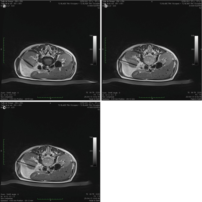
Fig. 16.5
Axial T2-weighted MRI images confirming position of cryoablation probe (1) (a), (2) (b), and (3) (c) in a left anterior renal tumor
Ideally the tip of the ablation probe in CA should be positioned 5 mm beyond the deepest margin of the tumor, when possible, to prevent inadequate ablation, as CA probes do not ablate beyond the tip of the probe. The ice ball and subsequently the ablation zone extend laterally. In the case of RFA, ideal placement of the electrode tip is at the deepest or distal border of the tumor. For RFA electrodes with deployable tines, multiplanar imaging confirmation of the tine positions after deployment is important to identify and correct if the tumor has been pushed away rather than penetrated by the deployed tines, if the tines are clustered together or unevenly deployed, or most importantly if one of the tines has extended into an undesirable location, such as into the collecting system or through the diaphragm [19].
Ablation Monitoring
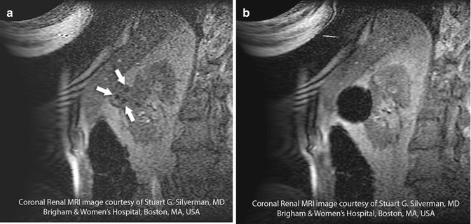
The ablation zone can be monitored in a continuous interactive manner with MRI similar to probe placement. This provides the advantage of direct observation of the size and configuration of the developing thermal ablation zone and permits the identification of any foci of residual viable tumor. The RFA ablation zone appears hypointense on T2-weighted and short tau inversion recovery (STIR) images [19], whereas the ice ball that develops with CA is represented by a signal void on both T1-weighted images (Fig. 16.6a, b) and T2-weighted images (Fig. 16.7a–c).
 < div class='tao-gold-member'>
 Optical Coherence Tomography for Prostate Cancer and Beyond
 Endoscopic Fluorescence Imaging of Bladder Cancer: Photodynamic Diagnosis and Confocal Laser Endomicroscopy
 Fluorescence Image-Guided Robotic Surgery
 Multiphoton Microscopy in Urologic Surgery
 Multiparametric Magnetic Resonance Imaging for Prostate Cancer
 Ultrasound-Guided Prostate Cryotherapy


Only gold members can continue reading. Log In or Register to continue
Related posts:
Optical Coherence Tomography for Prostate Cancer and Beyond
Endoscopic Fluorescence Imaging of Bladder Cancer: Photodynamic Diagnosis and Confocal Laser Endomicroscopy
Fluorescence Image-Guided Robotic Surgery
Multiphoton Microscopy in Urologic Surgery
Multiparametric Magnetic Resonance Imaging for Prostate Cancer
Ultrasound-Guided Prostate Cryotherapy
Stay updated, free articles. Join our Telegram channel
Full access? Get Clinical Tree
