Fig. 15.1
Patient on standard CT gantry, under general anesthesia lying prone on chest rolls with arms tucked. Note limited working space even in thin patients such as this (Arrow points towards head of patient)
The classic approach involves the interventional radiologist using a hand-guided needle placement based upon his/her understanding of the local target anatomy after creating a mental picture of the optimal placement. This requires a great deal of skill and experience. The best analogy is one of a gunnery sergeant trying to hit a faraway target by firing mortars and making fine adjustments to hit the target by honing in on the target. Initially one marks the entrance site on the patient’s skin surface with use of the CT software grid or a skin surface grid with embedded wires. Then, under maximal sterile barrier, an anesthesia needle is inserted at the site into the subcutaneous tissue and repeat CT imaging is performed confirming the position of the selected access site. A skin incision is made and the subcutaneous tissue may be dissected with a hemostat probe. We typically incrementally advance a 16 g blunt cannula and intermittently perform CT imaging to the periphery of the lesion. Intravenous contrast is sometimes administered to better localize the mass.
Once the position of the blunt cannula is confirmed with CT imaging, the blunt stylet is withdrawn from the cannula, and a combination of fine needle aspiration of the lesion with a 22 g Chiba needle and core needle sampling with an 18 gauge spring-loaded biopsy needle is performed. FNA (20–25 gauge needles) or core biopsy (16–18 gauge needles) may be used, but many interventionalists prefer use of a coaxial needle system allowing both FNA and core samples to be obtained at the same setting. This combination may result in a higher diagnostic yield although many physicians have abandoned the FNA. While leaving the blunt cannula in position as a guide, the thermal probe is inserted in tandem alongside the cannula and repeat CT imaging is obtained confirming adequate position of the probe. Ablation parameters and end points of treatment are device specific. Further discussion is beyond the scope of this chapter. See reference for additional information [9] (Fig. 15.2).
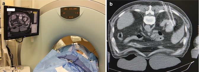
Fig. 15.2
(a) Image demonstrates 2 RF ablation probes in place with peripheral fiber-optic temperature probes along side. Video monitor displays right kidney with needle probes into the tumor mass and the temperature probe. Close-up shot of the monitor (b)
Advancements to Augment CT-Based Imaging and Guidance
Several CT-based imaging and guidance modalities have been developed and are commercially available but not widely utilized in clinical practice to date. These include conventional CT, CT fluoroscopy, and cone beam CT which can then be fused with other modalities such as positron emission tomography (PET) or real-time imaging modalities like electromagnetic navigation or ultrasound (Table 15.1).
Table 15.1
CT-based imaging and guidance modalities for renal ablation
System | Tip-target distance mean ± SD (if available) | Method of determining error |
|---|---|---|
Cone beam CT | 1.2 ± 0.4 mm [Tovar-Arriaga] | Phantom device |
PercuNav | 5.85 ± 4.48 [Venkatesan] | Patient biopsies liver/patient biopsies kidney |
3.4 ± 2.1 [Krucker] | ||
MAXIO robotic assistant platform | 6.5 ± 2.5 mm [Koethe] | Phantom |
PAKY-RCM | 1.66 mm [Solomon] | Phantom |
Veran | 2.2 ± 2.1 mm [Holzknecht] | Patient |
Ultrasound-guided motion-adapted instrument | 1.7 mm [Hong] | Moving phantom |
Ultrasound with integrated GPS | 1.8 mm [Hung] | In vivo canine |
Augmented reality system | 2 mm/5 mm [Nicolau] | Phantom/patients |
All of the techniques focus on visualizing a safe linear trajectory from a selected entry point on the skin surface to the target. From there, either manually or robotically, the needle is placed on the selected entry point on the skin, oriented to the correct angle, and inserted along the trajectory until the target is reached [11, 12].
Few centers have embraced these new technologies. Possible barriers include a high cost of entry as the equipment can be expensive to obtain, the need for additional training, and the lack of long-term data on the efficacy of such procedures. Additionally, operator comfort with present techniques is most likely a factor. However, it has been shown these initial entry costs may be recouped through long-term cost savings of CT-guided procedures which are estimated at saving between $3,625 and $5,155 per procedure [13–15].
Additionally, the large variety of available systems and a lack of understanding on how they compare to one another makes it difficult to choose a particular modality. The following review of many of the available technologies may prove helpful.
Cone Beam CT
Digital fluoroscopy systems can provide high-quality 3D reconstruction of cannulated structures but is unable to image soft tissues well [16]. Cone beam CT utilizes a rotating C arm with a large flat panel detector to capture over 200 X-ray images from varying angles in a process known as rotational angiography. This scan takes only 6 s and allows easy access to the patient. These images are then combined in what is termed cone beam reconstruction to create 3D CT-like volumes (Fig. 15.3). The resulting images can then be scrolled through similar to CT in order to plan appropriate needle pathways for interventional procedures. Three commercially available systems applying this technique are the DynaCT (Artis Zeego, Siemens Medical Solutions, Erlangen, Germany), Innovact (GE Healthcare, Schenectady, New York), and XperCT (Phillips Healthcare, Amsterdam, Netherlands). The images can be coupled with Artis Zeego iGuide technology (Siemens Medical Solutions, Erlangen, Germany) which assists in planning and mapping the trajectory. The tumor is first marked on coronal, axial, and sagittal planes. The skin entry point and trajectory are then chosen and the software displays the desired needle path which is then projected live on the patient with laser crosshairs (Fig. 15.4). Laser navigation systems like these have been shown to greatly improve target point accuracy. For instance, Moser et al. were able to decrease their target point error from a mean 3.5 mm freehand to 2.0 mm using a laser navigation system in spinal injection procedures [17]. Real-time fluoroscopy can then be used to compare the needle path with the planned trajectory. Manual needle placements allow for tactile feedback for the surgeon.
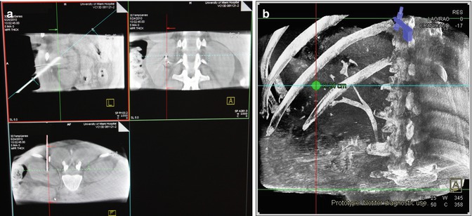
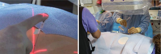
Fig. 15.3
(a) Sagittal, coronal, and axial views obtained with the cone beam CT. The angles of view can be altered on the computer to coordinate with “in-line” viewing “down the barrel” of the needle. These images are also utilized for 3D reconstructions (b)
Fig. 15.4
(a) Demonstration of fingertip control of needle placement using laser crosshairs (Artis Zeego, Siemens). (b) Note the open space in which to work utilizing cone beam Fluoroscopic technique
Tovar-Arriaga et al. additionally incorporated the DLR/KUKA Light Weight Robot III with the cone beam CT system. This robotic arm integrates the imaging and guidance technology and orients the needle itself while still utilizing manual insertion [12]. They measured their accuracy in a phantom model utilizing an Artis Zeego imaging system for error visualization. They determined the compilation of errors from the robot calibration, camera, and image construction to result in an average of 1.2 ± 0.4 mm from tip of the needle to the target distances [12].
This technique has been used by several centers in the ablation of small renal tumors with results showing recurrence-free rates >90 % [18, 19]. Additionally, it has successfully been implemented as a biopsy technique with accuracies as high as 95 % [20].
While allowing for fast and accurate soft tissue imaging, the cone beam CT imaging systems are still hindered by respiratory-dependent organ motion. To minimize the error, both the imaging and the procedure must be done at identical points in respiration which is usually held at end expiration. Additionally, while some real-time information of needle placement can be gathered through fluoroscopy, the majority of the imaging is performed intermittently.
Electromagnetic Navigation
Electromagnetic navigation (EMN) has been shown in phantom models to increase accuracy and reduce procedure time when combined with CT fluoroscopy guidance [21]. These systems consist of a field generator producing an alternating electromagnetic field which induces a voltage in small coils which have been placed into the needles. The resulting voltage is measured and used to calculate the current position and the orientation of the coil. Passive fiducial markers placed on the patient’s skin allow for fusion of prior CT imaging with real-time electromagnetic navigation. Holzknecht et al. implemented the Ultraguide (Tirat Hacarmel, Israel) electromagnetic tracking system for 50 image-guided biopsies and found the deviation between tip and target to be 2.2 ± 2.1 mm [22]. However, these results do not necessarily translate to improved outcomes for patients. In comparing CT-guided percutaneous lung biopsy alone to that with an electromagnetic navigation system in 60 patients, Grand et al. using the ig4 EMN system (Veran Medical Inc., St Louis, MO) found that adding electromagnetic navigation gave no statistical improvement in operative time, radiation dose, number of needle repositions, or diagnostic yield [23]. Additionally, the necessary hardware for these systems, including instruments with the appropriate coils, can be expensive.
Ultrasound CT Fusion
Several systems have been developed allowing for real-time imaging and feedback during percutaneous procedures [24]. One such system described by Venkatesan et al. combines electromagnetic device tracking and computed tomography (CT) with ultrasound (US) and FDG positron emission tomography (PET) imaging fusion [25]. This system fuses a prior PET/CT done on average 2 weeks before admission, with a navigation CT scan done with the patient in position and a sequence of tracked intraoperative US images using the PercuNav (Philips, Eindhoven, Netherlands) software. Utilizing the information from PET, a physician can better localize the target. Passive fiducial markers are placed near the entry site and are coregistered to the markers and radiopaque grid in the preprocedural CT. Intraoperatively, an electromagnetic field generator is placed about 30 cm from the sterile field. The electromagnetic tracking space is then registered to the navigational images by pointing the tracked needle to each fiducial at the interrupted point in ventilation and averaging the signal observed. During needle insertion they could then display PET/CT images, the fused real-time US images, and the electromagnetic-tracked needle location and trajectory. On 14 patients in which the system was used by Venkatesan et al., a verification CT scan showed a basic tracking error of 5.85 ± 4.48 mm. In performing this technique for 36 biopsies, 31 (86 %) of them were diagnostic. Additionally, one patient received hepatic RFA without complication of short-term recurrence at 56 days [25]. Krucher et al. used a similar system on 12 patients undergoing kidney tumor RFA ablation with an average tip to target error of 3.4 ± 2.1 mm [26].
< div class='tao-gold-member'>
Only gold members can continue reading. Log In or Register to continue
Related posts:
 Optical Coherence Tomography for Prostate Cancer and Beyond
 Endoscopic Fluorescence Imaging of Bladder Cancer: Photodynamic Diagnosis and Confocal Laser Endomicroscopy
 Multiphoton Microscopy in Urologic Surgery
 Endoluminal Ultrasonography
 Multiparametric Magnetic Resonance Imaging for Prostate Cancer
 Ultrasound-Guided Prostate Cryotherapy
Stay updated, free articles. Join our Telegram channel

Full access? Get Clinical Tree


