Procedure [Ref]
Target of navigation
Imaging modalities
Tracking systems
Modifications of navigation
Comments
Urinary stone
Fluoroscopy (two, in-line, iso-centric)
Mechanical
Ultrasound arm
All tested modifications work real time
Ultrasound (lateral, in-line)
Optical
Two cameras
Acoustic
Four piezoelectric sources
Collecting system
Fluoroscopy (2D, C-arm, 3D)
Mechanical
Mechanical arm with C-arm (locator)
(3D) Fluoroscopy real time
Ultrasound
US-guided
Robotic arm with fluoroscopy (PAKY)
EM real time
CT-based
Laser light
Robotic arm with CT (AcuBot)
CT not real time
Uro Dyna-CT
Electromagnetic
3D laser system
Dyna-CT/laser light not real time
Marker-based (inside out)
EM catheter
iPad-assisted
Renal parenchyma
Ultrasound
Attitude tracking
US-guided
CT not real time
CT
Marker-based
iPad-assisted
MRI
Based on significant improvement of imaging techniques and information technology (IT), the ability of surgeons can be significantly enhanced by integration of preexisting images on screen during video-assisted procedures. Data of 3D ultrasound, computed tomography (CT), or magnetic resonance imaging (MRI) can be recorded, segmented, and then displayed on the screen not only for the purpose of an exact diagnosis but also to augment surgeons’ spatial orientation [20, 21]. Image-guided surgery (IGS) correlates pre- or intraoperative images to the operative field in real time (Fig. 17.1). IGS aims to increase precision by providing a constant flow of information on a target area and its surrounding anatomical structures. One possibility to provide this information represents the use of augmented reality (AR). AR superimposes computer-generated models on a real video stream by aligning real with virtual image [35, 36].
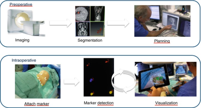
Fig. 17.1
The basic steps of imaging-guided surgery: using the example of marker-based navigation using the iPad
We present an overview about important projects on surgical navigation supported by the EAU Section of Uro-Technology (ESUT) focussing on AR-assisted percutaneous renal access (Table 17.2) starting with a short update on surgical navigation basics.
Table 17.2
Summary of experimental results of ESUT projects on percutaneous renal access
Centre | Study [Ref] | Tracking system | Model | Puncturing time (median) | Comments |
|---|---|---|---|---|---|
Heilbronn/Heidelberga | Marker-based with CT segmentation (+fluoroscopy) | Porcine kidneys embedded in ballistic gel (ex vivo) | 1.7 min (trainees) | 20 % reduction of radiation exposure for trainees | |
2.5 min (experts) | |||||
Electromagnetic (+fluoroscopy) | Porcine kidneys put in swine groin (ex vivo) | 15 s | Median distance to sensor 1.8 mm | ||
91 % single attempt access | |||||
Learning phase 30 punctures | |||||
Mannheimb | Laser-assisted tracking (+3D fluoroscopy) | Porcine kidneys put in chicken body (ex vivo) | 3.2 min | Longer times due to reassessment by Uro Dyna-CT during puncture (fluoro-time 0.35 min) | |
80 % single attempt | |||||
Bragac | Electromagnetic tracking for percutaneous access to renal collecting system [26] | Electromagnetic (+ureteroscopy) | Porcine kidney and ureter (in vivo) | 24 s (plus planning time of 13 s) | 47 s for resident (plus 16 s planning) |
Longer times for ureter access (51 s) | |||||
Cluj | Attitude tracking for percutaneous renal biopsy/focal therapy [31] | Attitude tracking (for ultrasound) | Gel model with sonographical visible target | 7 s | Higher accuracy by attitude tracking (1.0 mm vs. 3 mm distance to centre) |
Basics of Surgical Navigation for Percutaneous Renal Access
The main steps of image-guided surgery include (1) preoperative imaging and planning, (2) intraoperative imaging, and (3) tracking (Fig. 17.1).
Preoperative Imaging
Preoperative imaging is usually based on a multi-detector row CT or MRI (Table 17.1). In the case of nephrolithiasis requiring percutaneous renal access, according to EAU guidelines computed tomography is indicated as a preoperative diagnostic option to plan the procedure [37]. AR-based techniques, like iPad-assisted marker-based navigation, can use CT for segmentation and image-guided surgery (Fig. 17.1). Special software programs allow the display of data in three dimensions and fusing images of different modalities. The information from different modalities regarding the same anatomical region (kidney) can then be displayed on a single image. These images (augmented reality) represent the basis for planning of the procedure, but intraoperative image acquisition is mandatory for any surgical navigation tool [20, 21, 35, 36].
Intraoperative Imaging
The most popular image acquisition modalities used intraoperatively for percutaneous renal access are ultrasound and 2D fluoroscopy (Table 17.1) [1–6]. Actually, these imaging modalities are used mainly under manual control to guide instruments or needles. In contrast, computed navigation requires 3D data. Apart from ultrasound and 2D fluoroscopy, open MRI, 3D ultrasound, iso-centric 3D C-arm, and Uro Dyna-CT may be useful for intraoperative image acquisition for percutaneous renal surgery (Table 17.1) [15, 17–19, 24, 25, 27–29, 32, 33].
The major challenge of soft tissue navigation is registration and fusion of preoperative image data on intraoperative patient images, because the constellation and shape of unconstrained organs may change since planning and also during intervention. A nonrigid image-to-image registration of pre- and intraoperative image data may resolve the issue. Some authors superimposed 3D visualisation of the kidney on the endoscopic image with manual overlapping of the organ boundaries [35, 38, 39], but accuracy is limited because 3D reconstruction and endoscopic image are still displayed on a 2D screen. Point-to-point registration – as used with the iPad – may provide optimal accuracy as long as landmarks or fiducial markers can be spotted exactly in both image systems (Fig. 17.1). Percutaneous renal access entails the advantage that correct correspondence of AR and real view (i.e. on iPad) can be checked easily using the ribs as landmarks.
Tracking
Tracking devices link spatial information from imaging modalities, surgical instruments, or endoscope/ nephroscope by representing these actors in a single coordinate system. Various lithotripters have used different types of tracking modes to enable stone localisation (Fig. 17.2) [10–13]. Technical options include (1) optical tracking, (2) electromagnetic tracking, (3) attitude tracking, (4) acoustic tracking, and (5) marker-based tracking.
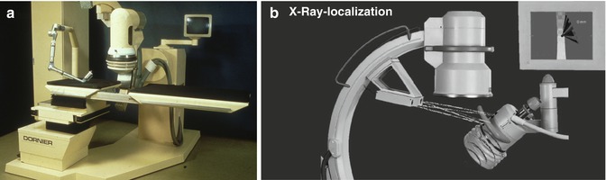
Fig. 17.2
Navigation in lithotripters for extracorporeal shock wave lithotripsy. (a) Dornier MPL 9000: articulated robot arm with integrated ultrasound probe for microprocessor-controlled positioning of the patient based on potentiometers in the joints of the arm (electromagnetic tracking). (b) Modulith SLK: combination of fluoroscopic localisation and 3D navigation using a camera system determining the position of the shock wave source in relationship to the stone seen on fluoroscopy (optical tracking)
Optical tracking is based on visual registration of the position of tracking bodies or sensors attached to an endoscope, instrument, or ultrasound probe usually using two or three cameras (Fig. 17.2b). This determines the exact position of the tip of a rigid instrument/endoscope/ultrasound probe in the OR room or accordingly inside the patient [20, 21, 40].
Electromagnetic tracking measures the position of small coils inside the patient without the need of direct line of sight. A magnetic field has to be generated around the patient. The sensor coil is attached to the tip of an instrument, endoscope, or ultrasound transducer [20, 21]. For percutaneous renal access, it has been fixed at the end of a steerable 5-DOF ureteral catheter [22, 23, 26]. The EMT sensor analyses the position of the coil and tracks the puncturing needle accordingly to facilitate a rendezvous manoeuvre (Fig. 17.3). Another possibility of EMT is the use of potentiometers placed at the joints of articulated arms (Fig. 17.2a). Magnetic tracking may be interfered by ferromagnetic objects like surgical table, instruments, or electrical-powered devices [20, 26, 41].
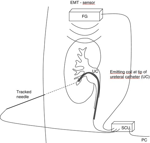
Fig. 17.3
Navigation used for percutaneous access to the kidney: electromagnetic tracking based on analysis of the position of the electromagnetic emitter attached to tip of ureteral catheter (UC) by EMT sensor at bedside who also tracks the puncturing needle
Attitude tracking or motion tracking uses an accelerometer to determine the actual spatial position of an ultrasound probe. Based on this, the lateral extension of a defined movement (attitude) can be determined and calculated [31, 42]. This allows the device to indicate precisely the specific position of the tracked device, such as the exact mid-position as indicated by the two blue LED lights (Fig. 17.4).
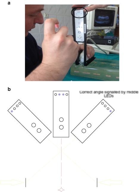
Fig. 17.4
Navigation used for percutaneous access to the kidney: attitude tracking by attaching an accelerometer (Nintendo WiiMote) to the ultrasound probe mounted in a special chassis. (a) Position of the probe can be displayed in real time on a computer. Manipulating ultrasound probe, landmark points (lateral rim of target) can be determined. Based on this the direction to targeted points (exact midline) are calculated and displayed by the tracking device (two blue central LED lights = black circle). (b) Schematic drawing of principle
Acoustic tracking uses supersonic piezoelectric emitters and sensors. These can be placed at rigid imaging devices (ultrasound probe, fluoroscopic C-arm) and at the patient site respectively the shock wave source coupled to the skin of the patient [13]. Similar to optical tracking, the relative position of emitters and sound receivers can be calculated to determine the exact position of stone and focal zone of the shock wave source.
Marker–based tracking utilises the information of the monocular video for tracking (Fig. 17.5). Based on the placement of navigation aids, the position and orientation of the tip of the endoscope or rear camera of the iPad in relation to the target organ can be calculated. Prior to image acquisition, navigation aids are attached near the anatomical target region [24, 25]. A surgical planning step localises these navigation aids in the computerised imaging data (CT).
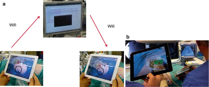
Fig. 17.5
Navigation used for percutaneous access to the kidney: marker-based tracking based on computed tomography carried out with patient in prone position with markers attached around the target area for puncturing a renal tumour. (a) Following segmentation of data, the server/laptop communicates with the iPad via WiFi. (b) Exact overlay of virtual pins and real navigation markers on the fused image on iPad indicates correct navigation process (here with demonstration of renal tumour for biopsy). Ultrasound is used as a real-time imaging modality
Post–processing segmentation includes definition of anatomical structures of interest providing important additional information, such as surgical trajectory, access, or stone localisation. Immediately prior to surgery, the navigation system is set up in the operating room (Fig. 17.1). During intraoperative patient-to-image registration, the respective tracking device is used to localise the navigation aids. Transformation for mapping objects of the image to the tracking device space is calculated, thus enabling visualisation of arbitrary anatomical structures in relation to puncturing needle respectively instruments [24, 25].
European Studies Using AR for Percutaneous Renal Interventions
Marker-Based iPad-Assisted Puncture of the Collecting System
A marker-based tracking principle previously described during laparoscopic radical prostatectomy [36, 43] was modified to puncture the collecting system prior to percutaneous nephrolithotripsy [24, 25]. Instead of placing navigation aids on the target organ (prostate), we placed coloured markers on the skin around the puncture area. Preoperative imaging consisted of multi-slice CT with the patient in prone position on a PCNL cushion exactly as during surgery (Fig. 17.1). The iPad is used as a camera, computer, and display; data are transferred to the central server/laptop through WiFi (Fig. 17.5a). As real-time imaging mode, we use 2D digital fluoroscopy. Based on experimental studies using porcine kidneys embedded in ballistic gel (Fig. 17.6), we applied this technique in a feasibility study of 19 patients focusing on success, time to puncture the collecting system, and radiation exposure of the patients.
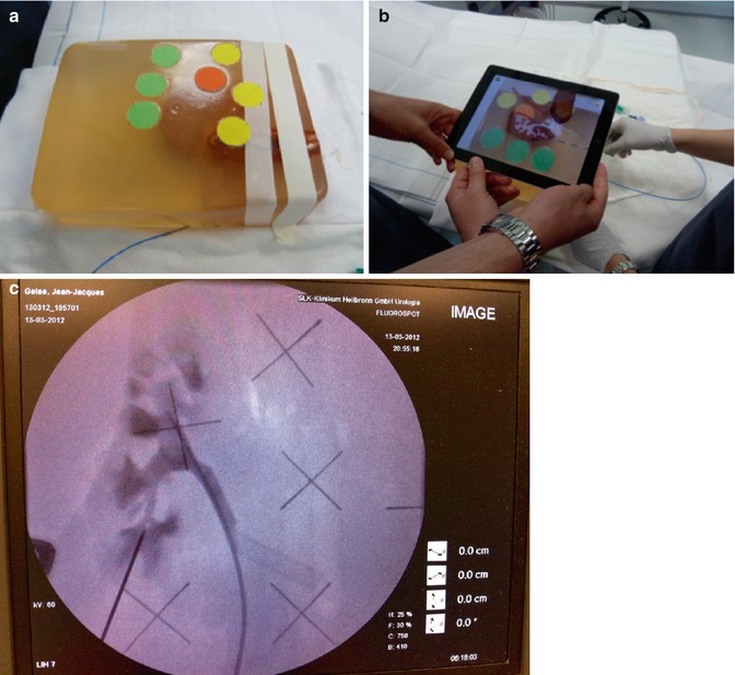
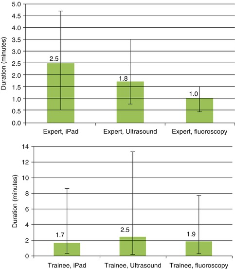
Fig. 17.6
Marker-based iPad-assisted puncture of the renal collecting system – experimental setup. (a) New model of porcine kidney embedded in dark-coloured ballistic gel. (b) Segmentation of the kidney and collecting system after multi-slice CT. (c) Puncture of the kidney with iPad assistance and verification of successful puncture by fluoroscopy. (d) Comparison of puncture times using iPad, ultrasound, or fluoroscopy. Shortest puncture times with iPad performed by trainees
In the in vitro study, image preparation time was 12 min and segmentation time 8 min. Puncture times for experts with iPad were longer compared to ultrasound or fluoroscopy (2.5 min. vs. 1.8 min. vs. 1.0 min.), whereas the trainees significantly benefited from the use of the iPad (1.7 min. vs. 1.9 vs. 2.5 min.) with 20 % reduction of radiation exposure (Fig. 17.6d, Table 17.2). For clinical use, improvements included, smaller radiopaque stickers instead of pins, iPad arm enabling single-surgeon use, and LED light at the back face of the iPad to guarantee optical visibility of all markers (Fig. 17.7c). In 13 of 19 cases, the collecting system was entered in a single attempt (average 1.5) with a radiation exposure of 377.5 μGym2. A matched-pair study which compares standard imaging (US + fluoroscopy) versus iPad-assisted puncture has been initiated (approved by Ethical commission, University of Heidelberg).
 Optical Coherence Tomography for Prostate Cancer and Beyond
 Endoscopic Fluorescence Imaging of Bladder Cancer: Photodynamic Diagnosis and Confocal Laser Endomicroscopy
 Fluorescence Image-Guided Robotic Surgery
 Multiphoton Microscopy in Urologic Surgery
 Multiparametric Magnetic Resonance Imaging for Prostate Cancer
 Ultrasound-Guided Prostate Cryotherapy


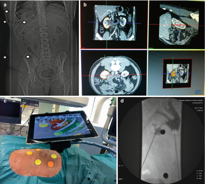
Fig. 17.7
Clinical experience with marker-based iPad-assisted puncture of the collecting system. (a) Preoperative prone multi-slice CT patient with complicated nephrolithiasis on the left kidney with markers placed around target area. (b) Semiautomated 3D segmentation of CT (performed by urologist). (c) Use of iPad during puncture with display of AR (ribs, kidney, colon, collecting system with stone). The iPad is fixed on a special arm with mounted LED light to enable optimal visualisation of the coloured markers. (d) Verification of successful puncture by 2D fluoroscopy
< div class='tao-gold-member'>
Only gold members can continue reading. Log In or Register to continue
Related posts:
Optical Coherence Tomography for Prostate Cancer and Beyond
Endoscopic Fluorescence Imaging of Bladder Cancer: Photodynamic Diagnosis and Confocal Laser Endomicroscopy
Fluorescence Image-Guided Robotic Surgery
Multiphoton Microscopy in Urologic Surgery
Multiparametric Magnetic Resonance Imaging for Prostate Cancer
Ultrasound-Guided Prostate Cryotherapy
Stay updated, free articles. Join our Telegram channel
Full access? Get Clinical Tree
