Fig. 4.1
Transabdominal ultrasound setup. The examiner sits or stands on the patient’s right. The ultrasound controls and monitor sit to the right of the patient’s head to allow easy use and viewing
In the operating room, the machine and attached monitor are typically placed on the side of the bed opposite the surgeon (Fig. 4.2). In our case, this is most commonly on the patient’s right. This has the disadvantage of requiring a third party to change machine settings when needed. If a remote monitor is available and displayed opposite the surgeon, the ultrasound machine can be placed next to the surgeon, covered with a sterile drape and settings changed by the ultrasonographer. During LUS, the use of the picture-in-picture feature is very helpful for matching external anatomic features with the corresponding ultrasound images.
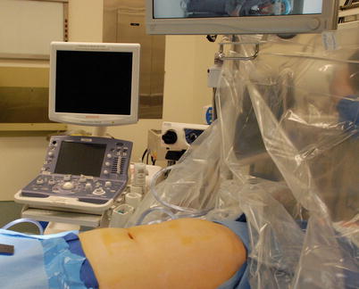
Fig. 4.2
Intraoperative ultrasound setup. The ultrasound machine and monitor are positioned to the patient’s right. The operating surgeon stands on the patient’s left. If the surgeon is positioned to the patient’s right, the machine is on the opposite side of the table
Terminology and Image Display
A common terminology and display protocol are essential to allow clear interpretation of images and a reference standard for displaying static images. There are two primary imaging planes, longitudinal and transverse (Fig. 4.3). The longitudinal plane for TAUS is the long axis of the body; for IOUS or LUS, it is the long axis of the organ. Longitudinal planes include a sagittal view, when the transducer is oriented anterior to posterior, or coronal, when oriented side to side. The transverse plane gives a cross-sectional image similar to the familiar axial image seen on computed tomography (CT).
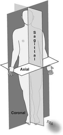
Fig. 4.3
Standard scanning planes for transabdominal ultrasound. Longitudinal planes include the sagittal and coronal planes. The single transverse plane is termed axial
Image orientation and annotation are critical for clear communication of ultrasound images. Image orientation is standardized. When scanning in the longitudinal plane, the direction of the patient’s head is oriented on the left side of the monitor screen (Fig. 4.4a). Scans done in the transverse plane are oriented such that the left side of the monitor image corresponds to the right side of the patient (Fig. 4.4b). Thus, when beginning a new scan, insure the transducer and monitor orientation are in alignment. Annotation should include the patient’s name, medical record number, date of the examination, and the plane of the image.
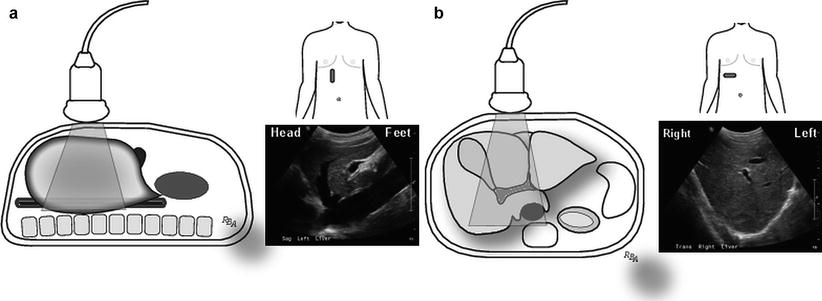
Fig. 4.4
Standard orientation and annotation of images is important for clearly communicating information represented by still images. (a) Transabdominal image with the transducer oriented in the longitudinal (sagittal) plane. By convention the image is oriented such that the patient’s head is in the direction of the left side of the monitor. (b) Transabdominal image with the transducer oriented in the transverse (axial) plane. By convention the image is oriented such that the right side of the patients’ body is oriented in the direction of the left side of the monitor
Image acquisition consists of several important steps to obtain interpretable images: coupling, transducer placement, and transducer manipulation.
Coupling and the Acoustic Interface
To obtain adequate ultrasound images, a path for transmission of sound waves between the transducer and the object being imaged is necessary. This path is called an acoustic interface; it is achieved through coupling. Coupling is a process that displaces air (an inefficient sound transmitter) between the transducer and the object with a more efficient transmitter. In TAUS, a gel is the most common coupling agent (Fig. 4.5); for IOUS/LUS, a little saline placed on the surface of the organ works well.
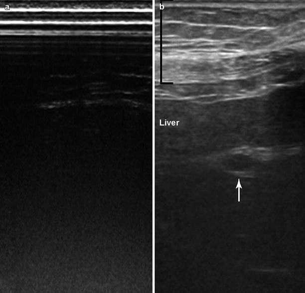
Fig. 4.5
Transabdominal ultrasound. (a) The transducer is placed on the skin without coupling gel. No discernible structures can be seen without an acoustic interface. (b) Gel is placed on the transducer and used to “couple” the transducer to the skin. This provides an acoustic interface that permits sound wave transmission and consequently an image. Seen in this image are the body wall (black bracket), the liver, and the left portal vein (white arrow)
Changing the thickness of the acoustic interface moves the transducer closer or farther from the object of interest, thereby altering the underlying image. This relationship allows several methods of scanning depending on the transducer’s relationship to the structure of interest (Table 4.1). These different scanning techniques have specific uses as outlined in this and later chapters. This is particularly important for objects of interest in the near field (between the focal zone and the transducer); when they are too close to the transducer, they cannot be seen or the image suffers from low resolution.
Table 4.1
Types of scanning
Contact |
Light contact |
Graded compression |
Deep compression |
Probe standoff |
Saline-filled bag/glove |
Saline immersion of organs (intraoperative/laparoscopic ultrasonography) |
Transducer Placement
The surgeons’ intimate knowledge of three-dimensional anatomy facilitates recognition and interpretation of ultrasound images. This familiarity allows pattern recognition of organs and structures based on past experience. Transducer placement is important to find “acoustic windows,” which are transducer placement sites that allow examination and recognition of the organ of interest. This requires considerable practice, patience, and a few tricks. However, matching the acoustic window with the surgeon’s deep understanding of the underlying anatomy makes learning this easier.
Transducer placement is determined by the type of scan being performed. These are reviewed in detail in the next sections. In addition, it is important to examine an organ or structure of interest in two planes to insure that the image is not due to an artifact. This includes both the longitudinal and transverse planes but also on occasion an oblique plane. Thus, transducer placement and movement is important to achieve this goal. Finally, the degree of transducer placement against the tissue alters the image and the scanning method may change based on the structure being imaged.
The next step for proper transducer placement is determining the type of contact between the transducer and the object for imaging (Table 4.1). Contact scanning occurs when the transducer is placed in direct contact with the tissue of interest. It can vary from light contact to deep compression, depending on the purpose of the scan. The majority of TAUS exams use light, direct contact scanning. If organ displacement is desirable during TAUS, for instance, to move a loop of bowel with gas lying over a structure of interest, then deep compression can be used to move it aside, exposing a better acoustic window. Similarly, light contact scanning is frequently used for liver scanning; occasionally deep compression is necessary to change the angle of viewing or to displace gas within an organ when viewing through the organ such as imaging the pancreas through the stomach or gastrocolic ligament. Probe (transducer) standoff scanning occurs when the probe is not in direct contact with the tissue of interest. Advantages of the probe standoff technique are outlined in Table 4.2. In probe standoff scanning, acoustic coupling is achieved by placing a fluid interface between the transducer and scanned structure. For instance, better images are obtained when scanning a superficial, subcutaneous object by placing a saline-filled glove on the skin and scanning through this to move the transducer 1–2 cm away from the surface of the skin. Probe standoff scanning is done frequently during IOUS/LUS, either by filling the abdominal cavity with saline or placing a saline-filled glove on the organ and scanning through the fluid-filled acoustic window.
Table 4.2
Probe standoff scanning advantages
Allows placement of the object of interest into the focal zone |
Eliminates artifacts due to an irregular scanning surface |
Objects within 1–1.5 cm of the scanning surface can be seen |
Superficial objects are seen with high resolution |
Lack of tissue compression eliminates distortion of underlying structures |
Provides more angles of freedom for scanning maneuvers |
Transducer Manipulation
After determining the type of probe contact, the next critical steps to master are the transducer movements (Table 4.3). Too much transducer movement is a common error early in the learning process. Most transducers have a wide viewing area, and movement of the transducer more than a few millimeters results in significant changes in the image. The novice becomes “lost” when the familiar patterns of a recognized image are no longer seen, requiring one to restart the process by identifying a recognizable structure or pattern. A second common error is lifting the transducer when moving it, which causes the image to disappear when the acoustic interface is interrupted, again causing the novice to lose a pattern they recognize. Lifting the transducer eliminates one of the unique and important features of ultrasound, that is, real-time image acquisition and viewing. To eliminate these errors, four basic types of transducer movement are outlined (Fig. 4.6).
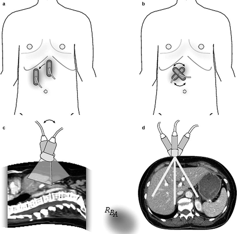
Table 4.3
Transducer movements
Sliding – transducer remains in contact with scanning surface; it is slid in longitudinal or transverse plane |
Rotating – transducer is spun clockwise or counterclockwise; central portion remains fixed to starting site |
Rocking – transducer is moved (rocked) parallel to the scanning plane |
Tilting – transducer is moved perpendicular to the scanning plane |
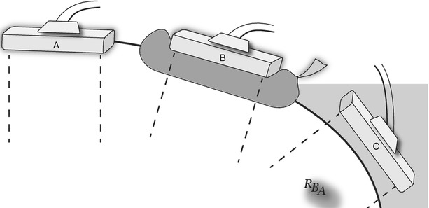
Fig. 4.6
Transducer movements. (a) Sliding. The transducer is moved without picking it up off the abdominal wall. (b) Rotating. The transducer is rotated clockwise or counterclockwise as if it were “pinned” to a central axis. (c) Rocking. The transducer remains in the same position relative to the skin while moving the back of the probe forward or backward in relationship to its long axis. This results in a series of images parallel to the scanning plane. (d) Tilting. The transducer remains in the same position relative to the skin while moving the back of the probe side to side relative to the long axis of the probe. This results in a series of images perpendicular to the scanning plane
Once the first acoustic window is identified and the transducer placed, the probe is moved by “sliding” it across the tissue surface (Fig. 4.6a), eliminating the need to lift from the scanning surface. Sliding can be done with the probe in a longitudinal or transverse orientation. Sliding gives a series of parallel images in relation to the original scan plane. Once the area of interest is identified, the probe can be rotated, rocked, or tilted to scan the object and its surrounding structures. Rotation involves spinning the probe as if the central part of the transducer was stuck to the tissue (Fig. 4.6b). This allows imaging of the structure of interest continually through the longitudinal, oblique, and transverse planes, allowing one to develop a three-dimensional image. During rocking, the transducer moves parallel to the original plane of imaging (Fig. 4.6c). Tilting is the result of moving the probe perpendicular to the original scanning plane (Fig. 4.6d).
These small movements allow scanning of large areas with very little transducer movement in relationship to its site of contact with the tissue. Detailed images of the structures of interest can be achieved without getting lost during the scanning process. This allows scanning of the target in at least two dimensions to insure the object is not an artifact. In addition, scanning in multiple dimensions in real time allows one to develop a three-dimensional understanding of the structure or organ of interest.
Finally, it is critical to develop a systematic scanning approach for each type of scan you do and for each organ. To insure a complete examination, this system should be followed fastidiously every time an ultrasound examination is performed.
Transabdominal Ultrasound
TAUS done by surgeons is typically a focused examination seeking specific information for diagnostic or therapeutic reasons. It does not substitute the need for radiological expertise or other imaging studies, but rather is complimentary to these.
TAUS usually begins with the patient in the supine position. The examiner is on the patient’s right side and the ultrasound machine is on the same side toward the head of the bed. A 3.5 MHz curvilinear transducer is the most common one used in adults. The curvilinear transducer requires a larger, flatter surface for optimal contact. When a smaller “footprint” (size of the contact surface) is necessary, such as viewing through an intercostal space, a phased array transducer can be used. Ideally, prior to TAUS, the patient should fast for 6 h. This decreases bowel gas and allows gallbladder distension.
Standard scanning planes for TAUS are those previously described: longitudinal (sagittal, coronal) and transverse. Most TAUS scanning is done with light contact with coupling accomplished with gel. When holding the transducer, it is helpful to stabilize your hand by placing the base of the hypothenar eminence against the body (Fig. 4.7). This allows for fine probe movement during the examination. The initial transducer placement depends on the type of study or organ of interest. The same is true for the initial transducer orientation. Transducer movement during TAUS includes all the techniques previously described.
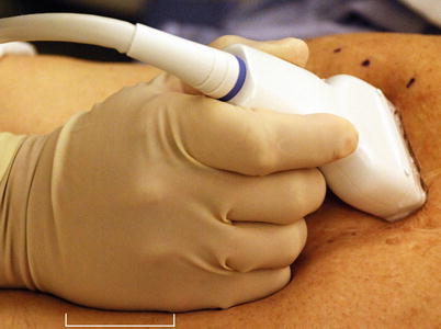
Fig. 4.7
During transabdominal ultrasound, it is helpful to hold the probe while lightly resting the hypothenar eminence (white bracket) against the body wall. This stabilizes the probe and allows for fine movements, steadies the image, and decreases fatigue
Liver Scanning Technique
Current transducers have a range of frequencies. A 3.0–3.5 MHz range is a good choice for most patients when evaluating the liver. A 5 MHz frequency may be better for very thin patients, while a 2.5 MHz frequency is helpful for obese patients or those with steatosis. Again, it is important to develop a systematic approach to scanning; it should be done every time. To begin liver imaging, place the probe transversely in the subxiphoid position and identify the hepatic veins as they join the vena cava. This is an easily recognized image that helps to orient the examiner (Fig. 4.8). If the patient has a steep, angulated costal margin, ask the patient to take a half to whole breath and hold it. This pushes the liver toward the costal margin, making the superior liver easier to see. Once this view is found, a systematic approach (Table 4.4) using a combination of transducer movements allows mapping of the segmental hepatic anatomy. For instance, a majority of the liver can be seen by rocking and tilting the probe while in the subxiphoid window (Fig. 4.9). Next, the probe is slid toward the left and then the right, allowing views of the remaining left and right livers, respectively. Upon completing the transverse views, the probe is reoriented in a sagittal plane and the process repeated. Sometimes the probe must be angulated sharply toward the head to scan beneath the costal margin. If this does not permit adequate viewing, an intercostal window allows access to structures hidden beneath the ribs. A smaller footprint probe is useful in this instance. Both an anterior and lateral approach through the costal margin may be necessary to image the structures of interest.
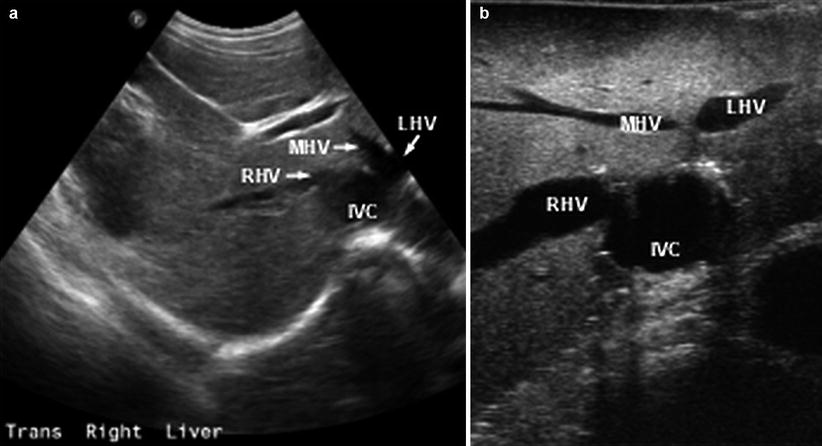
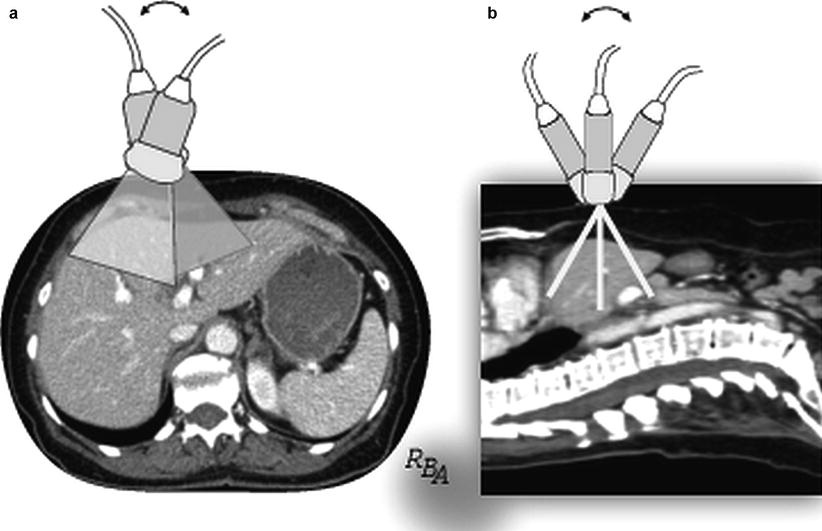
Fig. 4.8
Transabdominal ultrasound image with the transducer held transversely in the subxiphoid position. This allows a prototypical image of the hepatic veins as they join the vena cava (IVC). Right (RHV), middle (MHV), and left (LHV) veins are shown
Table 4.4
Stepwise approach to liver scanning: transabdominal
Identify hepatic veins |
Find junction with vena cava |
Follow to terminal branches |
Identify any anomalous branches |
Follow vena cava from hepatic vein branches to inferior liver |
Identify portal branches |
Find bifurcation, main, right, left portal veins |
Follow right and left veins to their segmental branches |
Systemic parenchymal scan |
Develop a standard scanning approach |
Examine all the parenchyma |
Note lesion location, size, and features |
Identify any vasculobiliary involvement or thrombosis |
Fig. 4.9
Transabdominal ultrasound with the transducer placed transversely in the subxiphoid position. Rocking (a) and tilting (b) the probe in this single position allow one to image a large portion of the liver with relatively little probe movement relative to the body wall
Biliary Scanning Technique
The transducer and techniques are similar to those described for the liver. Ideally, the patient should fast for 6 h prior to the study to allow maximal gallbladder distension. With the patient supine, position the probe subcostal in the midaxillary line while oriented in the sagittal plane. The initial step is to find the gallbladder. Slight sliding and tilting in this position allows a long axis view of the gallbladder (Fig. 4.10). Rotating the probe in the same position allows transverse and oblique views of the gallbladder. From here, several standard probe positions are helpful for complete biliary scanning (Fig. 4.11) [1]. Intercostal windows typically are necessary for complete biliary scanning. Rolling the patient into the left lateral decubitus position is important to distinguish whether gallbladder masses are stones (move with repositioning) or polyps (stationary with repositioning) and sometimes to get an adequate view of the extrahepatic bile duct.
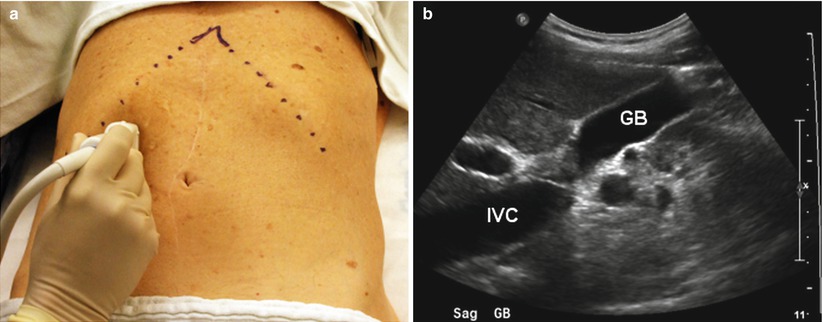
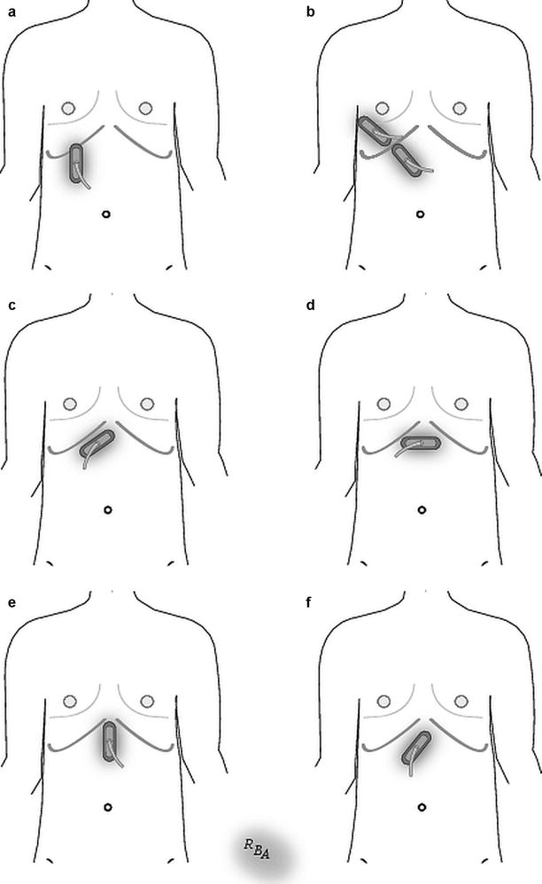
Fig. 4.10
Gallbladder imaging. (a) The transducer is oriented in the sagittal plane in the midaxillary line. (b) This allows a longitudinal view of the gallbladder (GB). Inferior vena cava (IVC)
Fig. 4.11
Standard transducer positions for transabdominal biliary imaging. (a) The probe is positioned sagittally in the right subcostal, midaxillary position to view the gallbladder. (b) Right intercostal space, oblique position allows gallbladder, right intrahepatic duct, and right portal triad imaging. Right epigastric, oblique position allows viewing of the proximal extrahepatic porta hepatis. (c) Right subcostal, oblique position shows the right and left hepatic ducts. (d) Subxiphoid transverse position shows the left lateral section bile ducts. (e) Subxiphoid midline, or right paramedian, sagittal position allows imaging of the mid to distal extrahepatic bile ducts. (f) The distal-most portion of the common bile duct is seen from a left oblique upper abdominal position (Adapted from [1])
The extrahepatic bile duct is recognized by its position anterior to the portal vein. Place the probe in a longitudinal plane approximately perpendicular to the right costal margin between the midaxillary line and the epigastrium (Fig. 4.11, position b). Identify the portal vein at the hilar plate and follow it caudally to identify the bile duct in a longitudinal view anterior to the portal vein (Fig. 4.12). Sliding the probe toward the midline while in a longitudinal or oblique position allows viewing of the distal duct (Fig. 4.11, positions e and f). If the duct is not visible in this position, the best view may be obtained by placing the probe in a longitudinal, subcostal, and midaxillary position while the patient is in the left lateral decubitus position. Views of the retroduodenal duct are difficult to obtain as they often are obscured by duodenal or bowel gas. The intrapancreatic duct is best seen in transverse section through the head of the pancreas; however, this can be difficult to obtain due to bowel gas. Unless dilated, small intrahepatic ducts can be difficult to see. Intercostal windows facilitate imaging the right intrahepatic ducts, while the left ducts are viewed from a left subcostal window.
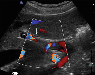
Fig. 4.12
Transabdominal ultrasound of the extrahepatic bile duct. The probe is positioned in the sagittal plane. The bile duct (white arrow) lies anterior to the portal vein (PV). Color Doppler is helpful to distinguish vascular structures from the bile duct
Pancreas Scanning Techniques
TAUS of the pancreas can be difficult due to bowel gas between the abdominal wall and the pancreas. The patient is examined in the supine position after fasting to minimize bowel gas. If the view still is impeded by gas, several other techniques can be used to improve the view. Deep inspiration and breath holding may push the liver below the costal margin where it can serve as an acoustic window to the pancreas. Compression scanning with deep pressure on the probe can push gas-filled structures aside. Placing the patient in a semi-upright position after drinking 500 ml of water may allow a viewing window through the fluid-filled stomach. A right lateral decubitus position may improve the image. Finally, the tail of the pancreas may be best seen from a left lateral flank view through the spleen.
The pancreas is difficult to find on TAUS. It is most easily identified by its relationship to surrounding landmarks. The transducer is positioned transversely in the subxiphoid, midline position. The pancreas is identified by first finding the vertebral body, aorta, vena cava, and the splenic vein junction with the superior mesenteric vein. The pancreas can be inferred by its relationship to these structures. Figure 4.13 shows the prototypical image used to identify the pancreas. Once the neck and body are seen, the remaining portions of the gland are examined in the transverse plane and then the longitudinal plane.
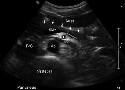
Fig. 4.13
Transabdominal ultrasound of the pancreas. The transducer is placed in the transverse plane in the midline just inferior to the xiphoid. This is the prototypical image of the vasculature surrounding the pancreas that facilitates its identification. The anterior border of the pancreas is denoted by the white arrows. The pancreas lies just anterior to the superior mesenteric vein (SMV) and the splenic vein (white line). Other vascular structures that comprise this prototypical image include the aorta (Ao), the inferior vena cava (IVC), and the superior mesenteric artery (*). The left renal vein (LRV) also can be seen
Open Intraoperative Ultrasound
Intraoperative ultrasound has become an indispensable part of abdominal surgery. It is a critical tool to evaluate and manage hepatic, biliary, and pancreatic diseases. IOUS has the advantage of being the only real-time, intraoperative imaging technique available in the operating room. Finally, it can be reused repeatedly throughout a procedure to reevaluate and guide the operation.
The ultrasound machine and monitor are placed on the side of the table opposite the ultrasonographer. Choosing the appropriate transducer type and frequency is determined by the nature of the examination and the target organ. If the transducer is sterilized, no cover is necessary and direct scanning without an acoustic interface is done. If a non-sterile transducer is covered by a sterile cover, gel must be placed into the cover around the probe to insure adequate coupling. IOUS, like TAUS, uses contact and standoff scanning techniques and similar probe movement and manipulation to obtain images. Unlike TAUS, IOUS scanning planes are in relationship to the organ being scanned, not the body, thus differing in some instances to conventional TAUS planes.
Liver Scanning Technique
A flat, side-viewing, linear array transducer is favored for liver scanning. The long footprint allows efficient imaging of the whole organ and gives a rectangular image of the underlying structures (Fig. 4.14). Images in this configuration make interventions, such as needle biopsy, relatively easier compared to a curvilinear array. The probe’s low profile allows easy access in limited working spaces between the liver, abdominal wall, and diaphragm. While current probes are multifrequency, scanning in the 7.5 MHz range has the most utility for liver IOUS. This frequency allows adequate penetration to view the whole organ while showing the very fine detail of intrahepatic structures. A lower frequency, 5 MHz, may be necessary for a larger, steatotic, or cirrhotic liver since this frequency results in deeper sound penetration to examine the depths of the parenchyma in these organs.
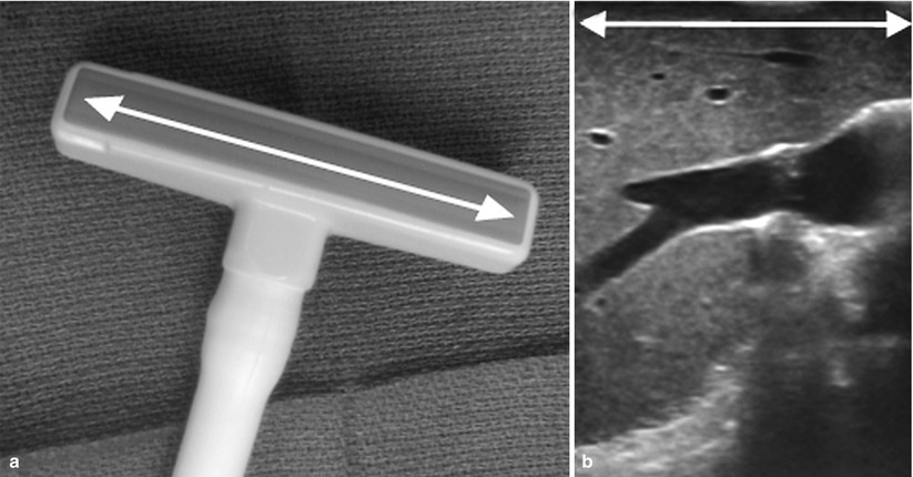
Fig. 4.14
(a) Intraoperative linear array transducer. This probe has a relatively large “footprint” due to its long crystal array (white arrow). (b) This results in a long, rectangular image
Similar to TAUS, a critical component for successful IOUS is developing a systematic scanning approach for the liver. Fastidious adherence to this system insures an adequate and thorough evaluation every time an examination is performed. The first step of this approach is identifying the segmental anatomy. Once each segment is mapped, an evaluation for known and occult lesions is undertaken, noting their location and relationship to the segmental anatomy and intrahepatic structures.
Hepatic IOUS begins with contact scanning (Fig. 4.15, position A). Moistening the liver’s surface with saline is sufficient to create coupling. The probe is placed in direct contact with the liver; knowing its exact position on the organ is an advantage of IOUS, making image interpretation easier. Contact scanning is useful for imaging most of the liver; however, it is of limited utility when a mass or structure is within 5–10 mm of the probe (Fig. 4.16). Thus, superficial areas directly beneath the probe represent a “blind spot” during contact scanning. Similarly, irregular surfaces (e.g., cirrhosis) make scanning difficult, leading to poor image quality. It is these circumstances when a probe standoff technique for scanning is of use (Fig. 4.15, positions B and C). Saline is an effective interface to establish an acoustic window between the probe and the surface of the liver for a probe standoff technique. With the transducer separated from the liver surface, superficial structures or the irregular surface are seen with better clarity and resolution than during contact scanning. Probe standoff scanning can be done in several ways as illustrated in Fig. 4.15. The difficulty with image resolution of superficial lesions by IOUS emphasizes the importance of combining inspection and palpation when examining abdominal organs, since these techniques are complementary to IOUS. Each of these examination methods should be used to insure complete evaluation of the liver.