Fig. 16.1
Ultrasound probes are designed with both ergonomics and imaging characteristics in mind. Handpieces can be shaped for a particular use, and straight and curved arrays provide different imaging qualities. (a) Linear transducers in two ergonomic configurations. (b) Curved array transducers in both open and laparoscopic varieties
Transducer Orientation
The ultrasound transducer produces an image of the narrow plane of tissue beneath it. The transducer of most open ultrasound probes is perpendicular to the cord and handle and is therefore described as having a “left” and “right” side (Fig. 16.2). The laparoscopic probe is oriented such that the transducer is in line with the shaft. The distal tip of the device is termed the “toe” and the proximal end of the transducer the “heel” (Fig. 16.3). The image on the ultrasound screen can be manipulated in regard to the “left-right” orientation viewed on the screen. Thus, the toe portion of the image can be on the right-hand side of the screen or on the left. This applies in a similar manner to an open probe. It is at the operator’s discretion as to which orientation to choose, and the preferred view will depend on how each individual visually processes the spatial relationship seen on the screen [8]. Either orientation is acceptable, but it is critically important to know the orientation prior to beginning a scan for accurate planning and execution of biopsy or ablation. The recommended technique for determining orientation of the probe is to place only the tip of the laparoscopic probe, or one side of the open probe, in contact with the tissue and then look at the screen to determine which side of the tissue is being projected (Fig. 16.4a, b). The orientation is now known and the image can then be reversed as needed.
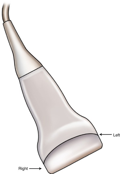
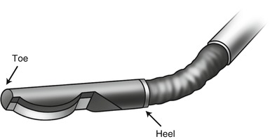
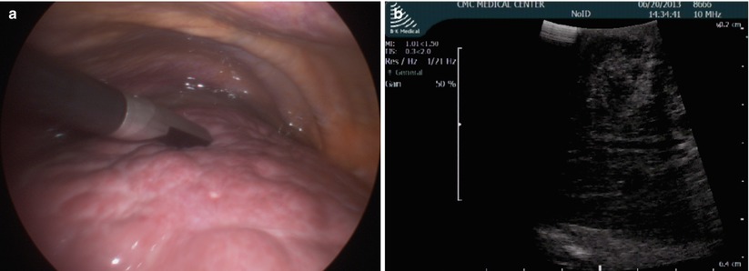

Fig. 16.2
Handheld ultrasound transducer marked left and right. The image on-screen can be flipped so that the right edge of the transducer corresponds to either the right or left edge of the screen to fit the user’s spatial orientation preference

Fig. 16.3
Laparoscopic transducer head shown in flexed position marked with heel and toe. The image on-screen can be flipped to fit the user’s preference

Fig. 16.4
(a) Intraoperative image of ultrasound toe touching the tissue. (b) A corresponding ultrasound image showing half of field with visible tissue, orienting the toe of the probe to the right of the screen
Transducer Head Position
The laparoscopic transducer can be flexed up and down as well as left to right. This allows for great flexibility in scanning an organ’s contour. Rigid laparoscopic ultrasound devices are available, but the limitations of movement make them inadequate for full hepatic ultrasound. A common pitfall is to place the transducer in contact with the tissue and then rotate the transducer head while stationary in order to scan the tissue. This results in large amounts of deep tissue scanned, but very little tissue scanned on the surface. Figure 16.5 shows the result of rotating the transducer head without moving across the tissue (Fig. 16.5). When this maneuver is performed sequentially at different positions along a path, it is very easy to think that all tissue along the path has been scanned. However, in reality this is not the case. Figure 16.6 illustrates how a superficial lesion can be missed entirely by placing the transducer in two positions and rotating while remaining in place (Fig. 16.6). Therefore, the recommended technique for scanning is to move the transducer over the tissue while keeping it parallel to the tissue. In this way, an equal amount of deep and superficial tissue will be visualized, reducing the chance of missed lesions at any depth (Fig. 16.7). With an open ultrasound probe, this error is easier to avoid by keeping the ultrasound probe flat on the tissue of interest.
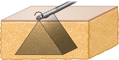
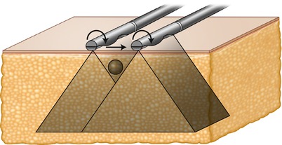
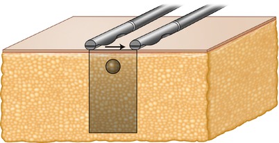

Fig. 16.5
The tissue is visualized perpendicular to the transducer. Rotation of the laparoscopic transducer without linear movement along the tissue visualizes a large amount of deep tissue with relatively little superficial tissue visualized

Fig. 16.6
When two sequential positions are used for transducer rotation, superficial lesions can be missed even though complete visualization is assumed. In this figure the laparoscopic transducer is rolled on the surface, moved laterally, and rolled in position again. A superficial mass is not imaged by either rolling motion, and if not picked up during the lateral movement of the probe, it will be missed entirely

Fig. 16.7
By moving the transducer linearly along the tissue while maintaining perpendicular position relative to the tissue surface, an equal amount of superficial and deep tissue is visualized, and a superficial lesion is located
There are circumstances when moving an ultrasound probe smoothly over the surface of an organ is not possible. For example, a cirrhotic liver is very challenging to transduce accurately because it is difficult to get all points of the transducer touching the surface at one time. This can be overcome with a “standoff” technique where saline solution is used to submerge the liver (Figs. 16.8 and 16.9). The ultrasound transducer can then be positioned above the surface without the loss of image quality that would result from transmission through air. This can also be very useful for superficial lesions located around corners. Figure 16.10 demonstrates the standoff technique allowing visualization of a lesion that would be difficult to access with a flexed ultrasound transducer (Fig. 16.10)
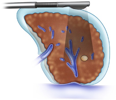
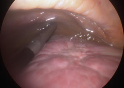
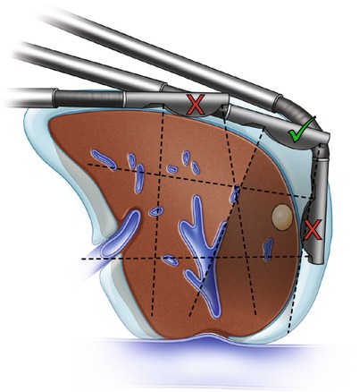

Fig. 16.8
The standoff technique used for a nodular cirrhotic liver using saline as an acoustic window. Ultrasound waves pass through the water layer and into the tissue seamlessly, providing a superior image

Fig. 16.9
A laparoscopic view of the standoff technique in use. Note the nodular appearance of the liver and the saline surrounding it. The transducer is submerged in saline in order to visualize pathology close to the surface of the liver

Fig. 16.10
The standoff technique used to visualize a superficial lesion high on the dome of the liver, which would be difficult to access directly with the ultrasound probe. This allows the lesion to be visualized through both the liver tissue and water layer with a clear image on-screen. The inferior (red X, top) probe position is the farthest a straight probe can achieve while maintaining contact directly with the liver tissue. The lesion is missed. The superior (red X, right) probe position requires the probe to be flexed around the edge of the liver to visualize the tumor, making targeting extremely difficult. The middle (green check mark) probe position allows the surgeon to visualize the tumor with a straight probe, making targeting for ablation most straightforward
Scanning Techniques
Regardless of the tissue scanning method employed, it is important that it be methodical and complete. With any organ, a scanning technique can follow anatomic landmarks within the tissue, such as vasculature, or can be performed in a standardized fashion along the surface of the organ. For liver ultrasound, two different approaches are recommended. The portal vasculature can be followed in a “pedicle” technique, or the surface of the liver can be followed in a “lawnmower” fashion. These techniques will be described for the liver in this section, but other organs in the abdomen can be scanned with similar techniques requiring only small modifications for anatomy.
Stay updated, free articles. Join our Telegram channel

Full access? Get Clinical Tree


