Fig. 10.1
Positioning and instruments used in robot-assisted total mesorectal excision. The patient is placed in a modified lithotomy position using a levitator with both arms fixed to the body trunk. Shoulder pads are used to prevent the patient from slipping downward (a). The instruments used for robot-assisted total mesorectal excision (b). A gut clamper is used to occlude the rectal lumen before irrigating and transecting the rectum (c). A 30-Fr Malécot catheter is inserted transanally to decompress the intraluminal pressure around the anastomosis (d)
10.4 Instruments
The da Vinci® Si surgical system (Intuitive Surgical Inc., Sunnyvale, CA, USA) is used for elaborate operations. A 12-mm camera port, 12-mm port, and four 8-mm da Vinci ports are used. The robotic instruments used include a 30-degree rigid endoscope, a straight rigid endoscope, a monopolar curved scissors, a fenestrated forceps, a Cadiere forceps, a double fenestrated forceps, a large clip applier, and a large needle driver (Fig. 10.1b). Additionally, an intestinal forceps with a ratchet and needle driver are used by the assistant surgeon.
A VIO®300D electrosurgical generator (ERBE Inc., Tübingen, Germany) is used. For monopolar applications, dry cut (50 W, effect 4) and forced coagulation (50 W, effect 3) are used; for bipolar applications, soft coagulation (60 W, effect 6) is used. A monopolar curved scissors and fenestrated forceps are connected to the monopolar and bipolar power sources, respectively.
Transection of the rectum and anastomosis are performed using a gut clamper (Kobe Biomedix Co., Ltd., Kobe, Japan), 45-mm linear stapler, and 29-mm circular stapler (Fig. 10.1c). For patients with anal stenosis or those undergoing super-low anastomosis in the anal canal, a 25-mm circular stapler is used. A 30-Fr Malécot catheter (C. R. Bard Inc., Covington, GA, USA) is inserted transanally to decompress intraluminal pressure around the anastomosis (Fig. 10.1d).
10.5 Port Placement
The patient cart is set up so that robot arm ③ is placed to the lateral side of robot arm ①. Manipulations in the abdominal cavity and pelvic cavity are performed using the dual docking technique (Figs. 10.2 and 10.3).
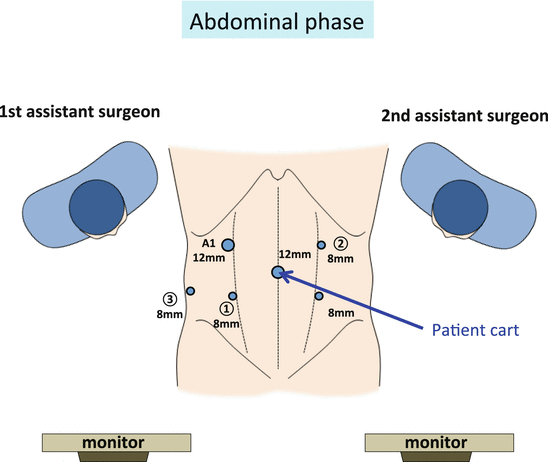
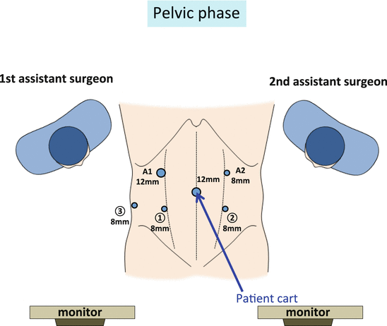

Fig. 10.2
Port placement and arrangement of the surgeons in the abdominal phase of robot-assisted total mesorectal excision. The patient cart is rolled in and positioned such that the center column, camera arm, the point approximately 3 cm cranial to the left anterior superior iliac spine, and camera port are aligned in a straight line. A1 the port used by the first assistant surgeon

Fig. 10.3
Port placement and arrangement of the surgeons in the pelvic phase of robot-assisted total mesorectal excision. The patient cart is rolled in and positioned so that the center column, camera arm, the midpoint between the pubis and the left anterior superior iliac spine, and camera port are aligned in a straight line. A1 the port used by the first assistant surgeon, A2 the port used by the second assistant surgeon
A 12-mm camera port is installed through the umbilicus, and pneumoperitoneal pressure is maintained at 10 mmHg. Manipulation ports are placed to ensure a distance of four or more fingerbreadths between each point and a distance of 15 cm or more from the superior border of the pubic bone.
8-mm da Vinci port ③ in the right flank: This is placed approximately 3 cm cranial to the right anterior superior iliac spine and immediately medial to the right paracolic gutter.
8-mm da Vinci port ① in the right lower abdomen: This is placed approximately 2 cm caudal to the midpoint between the camera port and the 8-mm da Vinci port ③. At the time of transection of the rectum, the port is changed to a 12-mm port, and the first assistant surgeon sitting to the right of the patient transects the rectum using a couple of linear staplers.
12-mm port in the right upper abdomen: This is placed approximately five fingerbreadths cranial to the 8-mm da Vinci port ①. In both abdominal and pelvic manipulations, the first assistant surgeon assists by inserting and removing gauze using intestinal forceps.
8-mm da Vinci port ② in the left lower abdomen: This is placed symmetrically to the 8-mm da Vinci port ①. This port is used only for pelvic manipulations, not for abdominal manipulations.
8-mm da Vinci port ② in the left upper abdomen: This is placed symmetrically to the 12-mm port. For manipulations in the abdominal cavity, the robotic forceps on arm ② is used. For pelvic manipulations, the second assistant surgeon positioned to the left of the patient holds the string wrapped around the rectum with the needle driver to linearize the rectum.
10.6 Surgical Anatomy
Loose connective tissue lies between the mesorectum and pelvic wall. By maintaining adequate tension between tissues, the loose connective tissue, which extends into a layer of foamy appearance, can be identified as the dissectable layer [7] (Fig. 10.4a, b).
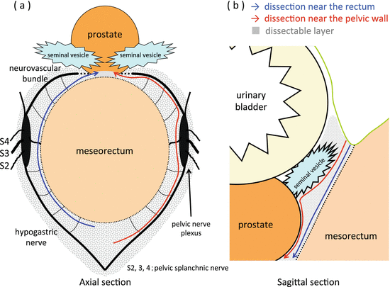

Fig. 10.4
The dissectable layer around the rectum. Axial section (a) and sagittal section (b) of the mesorectum and surrounding tissues are schematically illustrated. Loose connective tissue lies between the mesorectum and pelvic wall. By maintaining adequate tension between tissues, the loose connective tissue extending into a foamy appearance can be identified as the dissectable layer. In the dissectable layer, the decision whether to dissect near the mesorectum or near the pelvic wall should be based on the location and depth of the tumor
The autonomic nervous system, consisting of the lumbar splanchnic nerve, superior hypogastric nerve plexus, hypogastric nerve, pelvic splanchnic nerve, pelvic nerve plexus, and neurovascular bundle, runs longitudinally through the dissectable layer accompanied by adipose tissue and thin vessels (Fig. 10.5a). The autonomic nerve branch extending to the rectum passes through the dissectable layer toward the mesorectum. On dissecting the dissectable layer or the rectal branch of the autonomic nerve passing through the dissectable layer, the foamy loose connective tissue loses tension between the two planes, contracts, and appears membrane-like (Fig. 10.5b, c). Both the mesorectum and pelvic wall appear to be covered by this membrane-like tissue. This membrane-like tissue may be recognized as Denonvilliers’ fascia, the pre-hypogastric nerve fascia, or the proper rectal fascia, depending on the location. These membrane-like structures can be created artificially by dissecting the foamy loose connective tissue (i.e., the dissectable layer) (Fig. 10.5c).
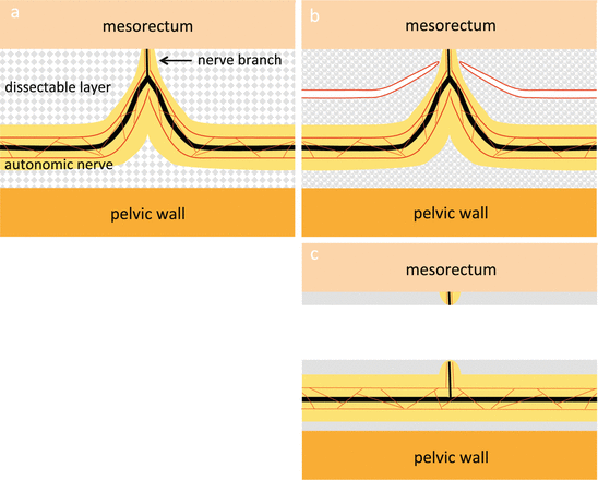

Fig. 10.5
The relationship between the autonomic nerve and the dissectable layer. The autonomic nerve runs within the dissectable layer accompanied by adipose tissue (yellow paint) and thin vessels (red line) and is pulled toward the mesorectum by the nerve branch (a). After cutting the nerve branch at the peak of pulled autonomic nerve, the dissectable layer contracts and the autonomic nerve is preserved (b, c)
In the dissectable layer, the decision whether to dissect near the mesorectum or near the pelvic wall should be based on the location and depth of the tumor (Fig. 10.4a, b).
10.7 Creation of the Operative Field
Abdominal phase: During mobilization of the upper rectum and colon, the first assistant surgeon grasps and elevates the fatty appendage of the colon or vascular pedicle of the sigmoidal vessels using the intestinal forceps. Then the Cadiere forceps on arm ③ is used to grasp and elevate the fatty appendage of the rectum or the inferior mesenteric artery (IMA) to create a surgical plane (Figs. 10.8a and 10.17a). With the fenestrated forceps on arm ②, the tissue is manipulated to maintain adequate countertraction.
Pelvic phase: The second assistant surgeon grasps and pulls the string around the upper rectum with the needle driver to straighten the rectum (Fig. 10.18).
Dissection posterior to the rectum (Fig. 10.6b): The fenestrated forceps on arm ② is guided into the pelvic cavity via the space behind the sigmoid colon. The second assistant surgeon pulls the rectum ventrally to straighten it, and the double fenestrated forceps on arm ③ is used to push the posterior wall of the mesorectum in the ventral direction to stretch the posterior wall of the rectum. The posterior wall of the rectum is then lifted ventrally or the loose connective tissue on the pelvic side is grasped and pulled dorsally using the fenestrated forceps on arm ② to visualize the dissectable layer.
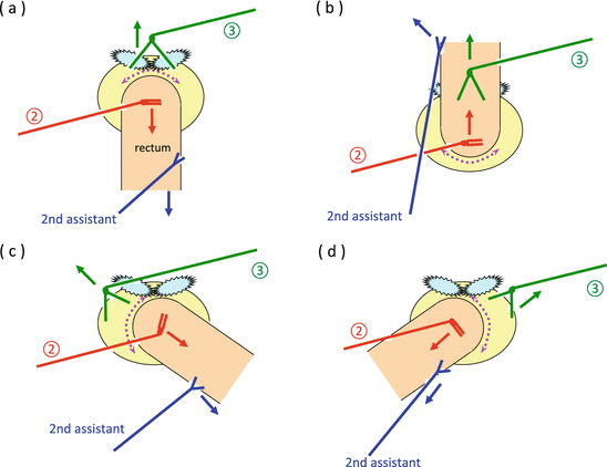
Fig. 10.6
Creation of the operative field around the rectum. The second assistant surgeon grasps and pulls a string wrapped around the upper rectum with the needle driver to straighten the rectum. The standardized procedures to create the operative field anterior to the rectum (a), posterior to the rectum (b), left to the rectum (c), and right to the rectum (d) are schematically illustrated. ② the fenestrated forceps on arm ②, ③ the double fenestrated forceps on arm ③
Dissection of the right side of the rectum (Fig. 10.6d): The second assistant surgeon pulls the rectum in the left cranial direction to straighten the rectum, and the opened double fenestrated forceps on arm ③ is used to push up the right anterior pelvic wall using friction force. With the fenestrated forceps on arm ②, the right side of the mesorectum is manipulated in the left cranial direction to visualize the dissectable layer.
Dissection of the left side of the rectum (Fig. 10.6c): The second assistant surgeon pulls the rectum in the right cranial direction to straighten the rectum. Then the opened double fenestrated forceps on arm ③ is used to push up the left anterior pelvic wall using friction force. With the fenestrated forceps on arm ②, the left side of the mesorectum is manipulated in the right cranial direction to visualize the dissectable layer.
Dissection anterior to the rectum (Fig. 10.6a): The second assistant surgeon pulls the rectum in the cranial direction to straighten the rectum. The opened double fenestrated forceps on arm ③ is then used to push up the seminal vesicles and prostate gland in male patients or the uterus and posterior wall of the vagina in female patients. With the fenestrated forceps on arm ②, the anterior surface of the mesorectum is manipulated in the dorsocranial direction to visualize the dissectable layer.
10.8 Procedure
10.8.1 Robotic Total Mesorectal Excision (TME)
10.8.1.1 Creation of a Wide Operative Field
In female patients, initially, the uterus is sutured to the abdominal wall using 2-0 Prolene. In male patients, if necessary, the vesical peritoneum is fixed to the abdominal wall after incising the peritoneal reflection.
The patient’s head is tilted downward by approximately 15° until the small intestines move out of the pelvis, with the right side slanted approximately 5° lower. After moving the omentum and transverse colon to the epigastric region, the mesentery and small intestines are moved to the right abdominal area as if turning a page of a book, enabling visualization of the duodenum, root of the IMA, left abdominal area, and pelvic cavity (Fig. 10.7). As there is a risk that the axis of the forceps on arm ③ can push the small intestine in the dorsal direction and crush it, the small intestine moved to the right side of the abdomen is placed cranial to da Vinci port ③ (Fig. 10.7b).
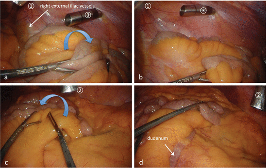

Fig. 10.7
Creation of a wide operative field. The mesentery and small intestines are moved to the right abdominal area as if turning a page of a book, enabling visualization of the duodenum, root of the IMA, left abdominal area, and pelvic cavity (a, c, d). There is a risk that the axis of the forceps on arm ③ can push the small intestine in the dorsal direction and crush it; therefore, the small intestine moved to the right side of the abdomen is placed cranial to the da Vinci port ③ (b)
10.8.1.2 Docking of the Patient Cart (Dual Docking-1; Abdominal Phase)
The patient cart is rolled in and positioned such that the center column, the camera arm, the point approximately 3 cm cranial to the left anterior superior iliac spine, and the camera port are aligned in a straight line (Fig. 10.2).
The camera arm is fixed to the camera port, arm ③ is fixed to da Vinci port ③ in the right flank, arm ① is fixed to da Vinci port ① in the right lower abdomen, and arm ② is fixed to da Vinci port ② in the left upper abdomen.
The interval between the elbows of the robot arms is left wider than the width of a fist. Robot arm ③ is positioned so as not to touch the right thigh of the patient.
The operation is performed with a 30-degree rigid scope angled downward. The Cadiere forceps on arm ③ is used to create key traction, the fenestrated forceps on arm ② is then used to apply countertraction, and sharp dissection is performed using the monopolar curved scissors on arm ①.
10.8.1.3 Mobilization of the Upper Rectum
The fatty appendages on the right side of the sigmoid colon are grasped using the fenestrated forceps on arm ② and the Cadiere forceps on arm ③ and are pulled out from the pelvis to straighten the rectum. The vascular pedicle of the sigmoidal vessels is then grasped by the first assistant surgeon using the intestinal forceps and pulled in the left ventrocranial direction (Fig. 10.8a). The fatty appendage on the right side of the upper rectum is grasped using the Cadiere forceps on arm ③ and elevated in the left ventrocaudal direction; thus, the right surface of the upper mesorectum is well stretched (Fig. 10.8a). The left ventral traction applied by the first assistant surgeon using forceps and by the Cadiere forceps on arm ③ is slightly relaxed to confirm the curvature of the right pelvic peritoneum and the right surface of the mesorectum (i.e., the imaginary incisional line of the peritoneum). Then the right surface of the upper mesorectum is once again stretched and the imaginary incisional line is verified again (Fig. 10.8b). With the fenestrated forceps on arm ②, the right pelvic peritoneum is pulled in the right direction using friction force (Fig. 10.8c).
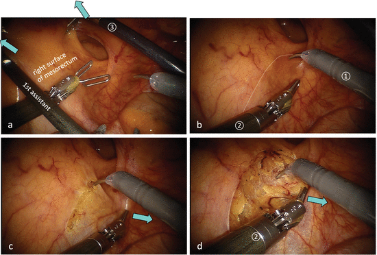

Fig. 10.8
The imaginary incisional line of the peritoneum on the right surface of the mesorectum. With the intestinal forceps in the first assistant’s hand and with the Cadiere forceps on arm ③, the right surface of the mesorectum is stretched out (a). The retraction of the mesorectum is slightly relaxed and the right surface of mesorectum is stretched out once again to verify the imaginary incisional line (white dotted line) (b). With the fenestrated forceps on arm ②, the right pelvic peritoneum is pulled in the right direction using friction force (c). After cutting the imaginary incisional line, the dissectable layer is clearly revealed (d)
Once the peritoneum on the right side of the upper rectum is incised slightly caudal to the promontory, carbon dioxide gas permeates beneath the peritoneum and the dissectable layer is clearly revealed (Fig. 10.8c). With the fenestrated forceps on arm ②, the cut edge of the right pelvic peritoneum is grasped and pulled to the right to widen the peritoneal incision. This stretches the foamy loose connective tissue between the mesorectum and pelvic wall and enables the right hypogastric nerve to be identified and verified (Fig. 10.8d). With the fenestrated forceps on arm ②, the right hypogastric nerve is manipulated slightly to the right, or the mesorectum is pushed ventrally, to reveal the dissectable layer between the mesorectum and right hypogastric nerve. The nerve branch toward the mesorectum is then dissected to preserve the right hypogastric nerve (Fig. 10.9). With the opened fenestrated forceps on arm ②, the posterior surface of the mesorectum is lifted in the ventral direction to stretch the loose connective tissue posterior to the rectum, the dissectable layer is dissected caudally from the posterior to posterolateral direction in the manner of a swinging pendulum (Fig. 10.9c), and the left hypogastric nerve is identified and preserved. When feasible, the posterior dissection of the mesorectum proceeds up to the interior surface of the peritoneum on the left side of the upper mesorectum in this step.
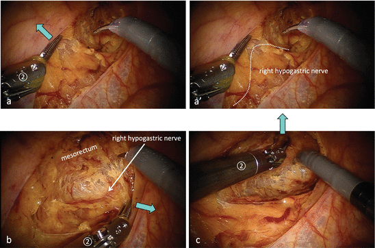

Fig. 10.9
Dissection behind the mesorectum. The right hypogastric nerve is surrounded by adipose tissue through which thin vessels run longitudinally and is pulled toward the mesorectum by the nerve branch (a, a′). With the fenestrated forceps on arm ②, the right hypogastric nerve is manipulated slightly to the right (b) or the mesorectum is pushed ventrally (c) to reveal the dissectable layer between the mesorectum and right hypogastric nerve
10.8.1.4 Proximal Lymph Node Dissection, Transection of the IMA, and Mobilization of the Mesocolon
The vascular pedicle of the sigmoidal vessels is grasped with the Cadiere forceps on arm ③ and pulled in the lateroventral direction to straighten the IMA, and the peritoneum around the IMA is grasped with the fenestrated forceps on arm ② and pulled in the lateral–ventrocranial direction to apply countertraction to the peritoneum at the root of the mesocolon (Fig. 10.10a, b). The peritoneum is incised approximately 5 mm medial to the IMA in the cranial direction, and then the loose connective tissue between the IMA and aorta is stretched out, appearing as foamy layer, allowing the superior hypogastric nerve plexus to be identified (Fig. 10.10c, c′). The nerve branch toward the IMA is dissected between the IMA and superior hypogastric nerve plexus.
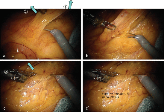

Fig. 10.10
Dissection behind the IMA. The vascular pedicle of the sigmoidal vessels is grasped with the Cadiere forceps on arm ③ and pulled in the lateroventral direction to straighten the IMA, and the peritoneum around the IMA is grasped with the fenestrated forceps on arm ② and pulled in the lateral and ventrocranial direction to apply countertraction to the peritoneum at the root of the mesocolon (a, b). The loose connective tissue between the IMA and aorta is stretched into a layer of foamy appearance, allowing the superior hypogastric nerve plexus to be identified (c, c′)
The peritoneal incision is extended cranially, and the proximal margin for lymph node dissection is set cranial to the root of the IMA. With the Cadiere forceps on arm ③, the IMA is grasped and pulled in the ventrolateral direction. With the fenestrated forceps on arm ②, the descending mesocolon is lifted in the ventral direction, or the loose connective tissue is grasped and pulled in the dorsal direction, to visualize the dissectable layer (Figs. 10.10c and 10.11). The dorsal side of the mesocolon is dissected laterally and cranially to preserve the left ureter. The nerve branch from the right lumbar splanchnic nerve toward the IMA is dissected and the right lumbar splanchnic nerve is spared. The left lumbar splanchnic nerve can be identified being pulled toward the lateral margin of the IMA (Fig. 10.12).
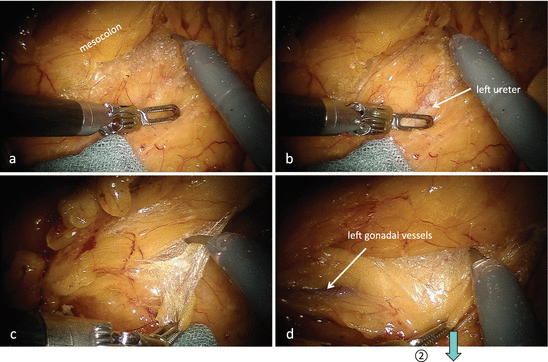
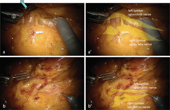

Fig. 10.11
Dissection behind the mesocolon. With the fenestrated forceps on arm ②, the descending mesocolon is lifted in the ventral direction, or the loose connective tissue is grasped and pulled in the dorsal direction to visualize the dissectable layer

Fig. 10.12
Relationship between the IMA and bilateral lumbar splanchnic nerves. The nerve branch from the right lumbar splanchnic nerve toward the IMA is dissected and the right lumbar splanchnic nerve is spared (a, a′), and then the left lumbar splanchnic nerve can be identified being pulled toward the lateral margin of the IMA (b, b′)
The IMA held by the Cadiere forceps on arm ③ is then manipulated in the dorsocaudal direction to allow visualization of the ventral side of the IMA. With the fenestrated forceps on arm ②, the fatty tissue surrounding the lymph nodes slightly peripheral to the root of the IMA is grasped and lifted together with the peritoneum, followed by lymph node dissection up to the root of the IMA along the nerve sheath covering the IMA and the left colic artery (LCA) (Fig. 10.12b, b′).
With the fenestrated forceps on arm ②, the nerve sheath around the IMA is grasped approximately 5 mm peripheral to the root of the IMA, pulled medially, and then cut with the monopolar curved scissors on arm ① to reach between the nerve sheath and the outer membrane of the IMA (Figs. 10.13b, c and 10.14b). The nerve sheath is dissected before the IMA is double clipped and transected. The left lumbar splanchnic nerve is then verified as being pulled toward the nerve plexus between the LCA and root of the IMA. Then the nerve plexus caudal to the pulled left lumbar splanchnic nerve is dissected and the LCA, inferior mesenteric vein (IMV), and mesocolon are separated from the root of the IMA and the left lumbar splanchnic nerve (Fig. 10.14a, a′ and c, c′).
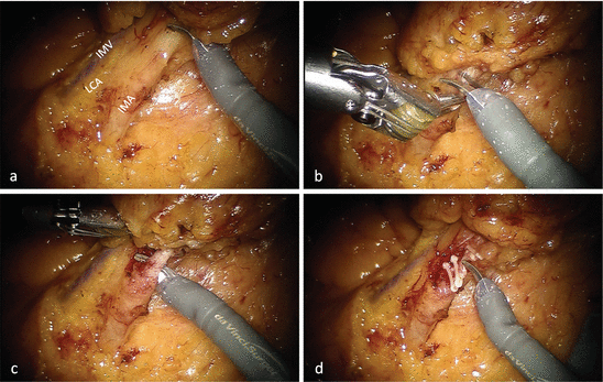
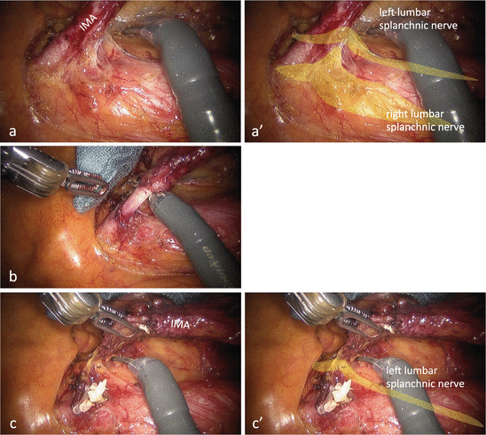

Fig. 10.13
Transection of the IMA peripheral to the branch off site of the LCA. With the fenestrated forceps on arm ②, the nerve sheath around the IMA is grasped, pulled medially, and then cut with the monopolar curved scissors on arm ① to reach between the nerve sheath and the outer membrane of the IMA (a–c). The nerve sheath is dissected before the IMA is double clipped and transected (d)

Fig. 10.14
Transection of the root of the IMA. Relationship between the IMA and bilateral lumbar splanchnic nerves (a, a′). The nerve sheath is dissected before the IMA is double clipped and transected (b). The left lumbar splanchnic nerve is pulled toward the nerve plexus between the LCA and root of the IMA (c, c′)
The removal side of the IMA stump is grasped with the Cadiere forceps on arm ③ and pulled in the ventral direction. The fenestrated forceps on arm ② is then used to elevate the descending mesocolon in the ventral direction, or to grasp and pull the retroperitoneum in the dorsal direction, to clearly expose the dissectable layer between the descending mesocolon and retroperitoneum and to separate it in the lateral direction. After confirming that the left gonadal vessels are set aside dorsally, the LCA and IMV are clipped and cut.
Separation of the mesocolon and retroperitoneum is performed up to the upper pole of the left kidney on the cranial side and up to the interior surface of the white line of Toldt on the lateral side.
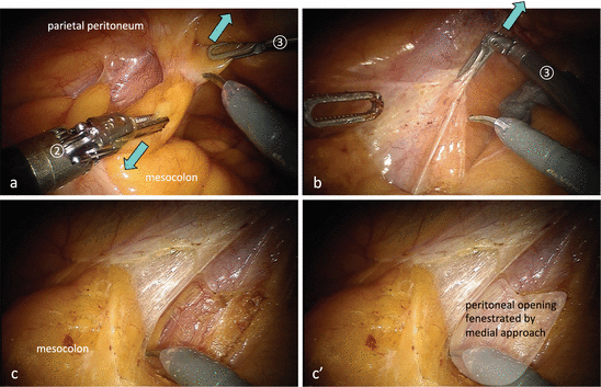
In almost all cases, the peritoneum on the left side of the upper mesorectum can be incised from the medial side and fenestrated to enable communication through to the lateral side (Fig. 10.15). This fenestration facilitates the following lateral approach.
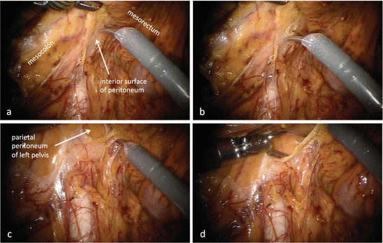

Fig. 10.15
Fenestration of the peritoneum on the left side of the upper mesorectum from the medial side. By connecting the dissected plane of the mesorectum and mesocolon, the line of dissection eventually reaches the interior surface of the peritoneum on the left side of the upper mesorectum (a). This white opaque membrane is incised intentionally from the medial side and fenestrated in order to communicate with the lateral side of the rectum (b–d)
10.8.1.5 Lateral Approach
With the Cadiere forceps on arm ③, the left parietal peritoneum covering the left psoas muscle is grasped and pulled in the lateral–ventrocaudal direction (Fig. 10.16a). Using the intestinal forceps, the first assistant surgeon then pulls the fatty appendage of the distal descending colon in the medial–cranial direction. With the fenestrated forceps on arm ②, the fatty appendage of the sigmoid colon is pulled in the medial direction to create countertraction, and the physiological adhesion with the left parietal peritoneum is dissected, and the peritoneal opening fenestrated from the medial side can then be identified (Fig. 10.16b, c, and c′). With the fenestrated forceps on arm ②, the fatty appendage of the distal descending colon is grasped and pulled in the medial direction, applying tension to the left paracolic gutter. The peritoneal incision line is then extended cranially along the white line of Toldt, thus completing mobilization of the distal descending colon.

