Fig. 18.1
Laparoscopic, hand-assisted, ultrasound-guided ablation of a hepatic malignancy. The patient had undergone a sigmoid resection and already had a lower abdominal hand port in place. Notice the surgeon is performing the procedure by looking back over his shoulder in the opposite direction
“Computerized Proprioception”
There are several commercially available computer-assisted navigational systems currently available, or under development, which have been developed specifically with liver and pancreas surgeons in mind. These systems include those produced by InnerOptic Technology (Hillsborough, NC), Pathfinder Technology (Nashville, TN), and CAScination AG (Bern, Switzerland). They all share some technical design characteristics, and even have some identical third-party components in common, but perhaps nothing more important than the similar concept behind the hardware. Essentially, these systems allow the computer to “know” where certain things are in space, such as a biopsy needle, an ablation antenna, or an ultrasound handpiece transducer. For lack of a better term, we might call this computerized proprioception. We begin by creating a three-dimensional “space” in the computer construct and allow the computer to place certain items in correct position and orientation, in this case an ultrasound probe and its corresponding ultrasound 2-D image. The computer then can add additional objects into that space in a location and orientation determined by the tracking system (also called the localization system) that it employs [1]. These objects, ranging from biopsy needles to microwave ablation antennae to surgical instruments, are computer-generated models (or avatars) of the actual instruments (see Fig. 18.2). This allows the surgeon to visualize the particular instrument relation to the ultrasound image and target lesion long before intersecting the plane of the ultrasound. (Remember that the surgeon does not normally see the antenna once it disappears into the target organ, until it crosses the ultrasound plane. Even then, it is often difficult to actually “see” the instrument.) Early systems utilized actual mechanical arms or calipers, which relayed information about instrument position to the computer to determine the location and orientation of certain items held in those arms. These systems utilized what is referred to as “mechanical digitizers” in order to relay positional information about the end instrument’s location and position to the computer [1] (see Figs. 18.3 and 18.4). One of these systems, which was developed at the University of North Carolina, Chapel Hill, Department of Computer Science, even added stereoscopic three-dimensional goggles (or head-mounted displays) to allow the surgeon to “look” directly at the target organ, rather than at a television monitor [2, 3].
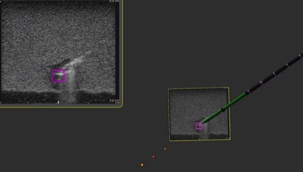
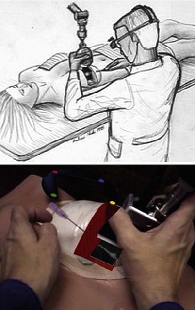
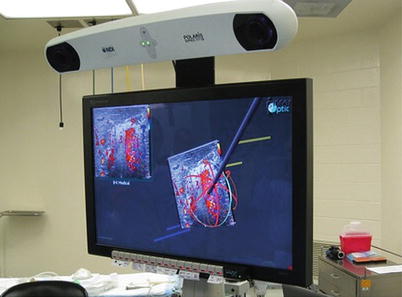
Fig. 18.2
Ultrasound guidance system image including 2-D ultrasound image in the left upper corner and stereoscopic 3-D image with microwave antenna avatar in the center. Notice the purple square target on the ultrasound image
Figs. 18.3 and 18.4
Breast biopsy system (ca 1996). A mechanical arm is used to track the position and orientation of the ultrasound probe, and the live U/S scan appears inside the breast, via an augmented-reality head-worn display. Left: conceptual sketch (Courtesy of Andrei State). Right: view from the head-mounted display, showing the U/S scan on a breast phantom, with an aspiration needle (Courtesy of Andrei State)
Although functional and certainly revolutionary, these systems had the drawback of being somewhat bulky and impractical for certain OR environments. With the advancement of technology, infrared cameras and optical sensors became the systems of choice for several of the image guidance systems and made the mechanical arms somewhat obsolete. These systems, collectively termed optical tracking systems (OTSs), have been used by the above-mentioned companies, yet the actual hardware (infrared camera and optical reflectors) was developed by a third-party company (Northern Digital Inc., Ontario, Canada). Several OTSs for orthopedic and neurosurgical procedures, as well as for general surgery, are currently available and all share certain similar tracking components, although not all systems utilize ultrasound. The Brainlab® system (Feldkirchen, Germany), for example, uses CT and MR imaging of the patient’s skull and brain along with an optical tracking system to help perform complex and precise neurosurgical procedures.
At least two companies have used similar strategies specifically for computer-navigated liver surgery, namely, Pathfinder® (Nashville, TN, USA) and CASination® (Bern, Switzerland). Both of these companies utilized sophisticated computer software to first construct complex 3-D models of each patient’s liver, including vascular anatomy and tumor characteristics. Both systems incorporate an OTS described above to co-register the patients’ actual liver and surgical instruments to the CT-based, computer-generated, 3-D model of the patient’s liver on a video monitor. In this way, the surgeon is able to “see” how close a particular instrument is to certain vital structures such as a major portal vein branch or hepatic vein. Both of these systems have been employed in actual human clinical surgeries for open hepatic resections and/or ablations with remarkable efficacy. These systems depend on static, preoperative CT- or MR-generated models rather than real-time intraoperative ultrasound (IOUS). With the mobilization and manipulation of the liver during open surgery, there often is distortion of the actual organ and the relationship of, say, a tumor to internal hepatic structures. Furthermore, there is continual movement of the patient’s liver during surgery from mechanical ventilation and diaphragmatic motion. As such, it was critical for these navigation systems to integrate live ultrasound.
The first system to successfully integrate real-time intraoperative ultrasound and an OTS for the purpose of liver surgery was produced by InnerOptic (Hillsborough, NC). This system grew out of the earlier research in the Department of Computer Science at the University of North Carolina, Chapel Hill, and has undergone multiple improvements and modifications since the first prototype was developed, some out of trial and error and some out of continuous improvements in hardware technology [2, 3]. The initial systems utilized rather large infrared cameras and optical LEDs mounted on clip-on adaptors for the ultrasound handpiece and the microwave ablation antennae (see Fig. 18.5). Yet this system proved functional enough to produce significant targeting improvements both in the laboratory setting and, after multiple generations of refinements and modifications, in the operating room. This data was presented at the American Hepato-Pancreato-Biliary Association annual meeting in 2008 and subsequently published, demonstrating an improvement in targeting of small phantom tumors in gelatin models by both experience and novice operators [4] (see Fig. 18.6). Furthermore, this system was shown to be both accurate and safe in an actual OR environment consisting of open hepatic ablation procedures [5]. Once again, lessons learned in both the laboratory and in the OR led to design modifications and improvements. Some of the other systems, previously described, which initially relied solely on preoperative CT or MR eventually modified their systems to include ultrasound. These systems now allow the surgeon to visualize both the preop CT mapping of the liver with real-time intraoperative ultrasound, all on a single flat-panel monitor (see Fig. 18.7).
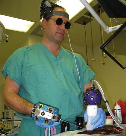
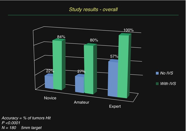
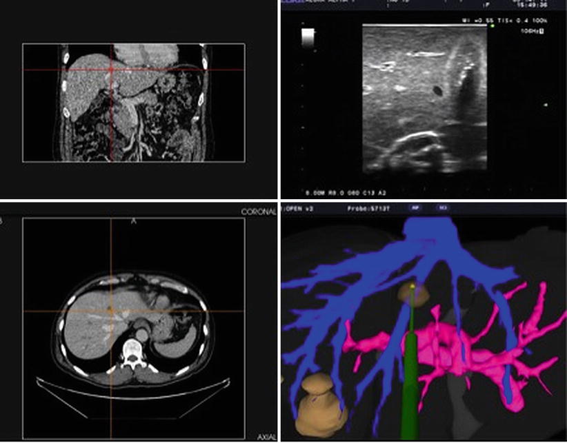
Fig. 18.5
Early guidance system prototype (ca. 2007) utilizing “active” optical sensors attached to ultrasound probes and microwave antennae and including a “head positional mount.” This system was modified and refined over time
Fig. 18.6
Results from targeting studies utilizing a 3-D guidance system for ultrasound, with optical tracking, in gelatin agar targets
Fig. 18.7
Screenshot of a guidance system incorporating coronal and axial CT images, an ultrasound image, and a computer model of the hepatic vascular anatomy and phantom ablation antenna (Image courtesy of Pathfinder Technologies)
“What Do You Mean by 3-D?”
A bit of clarification is in order regarding what is meant by “3-D,” in ultrasound navigation systems. To begin with, most ultrasound transducers in use today by surgeons (to include BK Medical, Aloka®, and SonoSite®) all utilize a single linear array of crystals and therefore produce a single-plane, two-dimensional ultrasound image. Much more sophisticated ultrasound systems utilize a grid of crystal transducers, or have a linear array, and a motor to quickly sweep it back and forth inside the ultrasound probe housing and can produce true multi-planar, three-dimensional ultrasound images. These machines are commonly used in obstetrics, where eager parents-to-be can see hauntingly detailed, 3-D images of their developing baby. However, when we speak of 3-D ultrasound guidance systems, we do not mean to imply a true 3-D ultrasound image; rather, some aspect of the navigation system is in 3-D. When we see a typical ultrasound image on a typical ultrasound monitor, we are seeing a 2-D image on a 2-D screen. And when we see a typical laparoscopic image, say during a laparoscopic cholecystectomy, we are seeing a 2-D image on a 2-D monitor. The InnerOptic system utilizes a high-resolution stereoscopic 3-D monitor that affords the surgeon depth perception not possible on even a high-definition 2-D television monitor. In these systems, the ultrasound image itself remains a 2-D image within a larger 3-D monitor “window.” Imagine, if you will, the ultrasound image is a sheet of paper floating in a virtual “box” in the 3-D monitor. That ultrasound image, as a sheet of paper, can be rotated and adjusted by the surgeon to the optimal position for the procedure. The computer then can a 3-D computer-generated model of the particular device in the precise position and orientation determined by the systems tracking components. Essentially, there are both 2-D and 3-D components within a 3-D space. The combination of these elements gives the surgeon the information needed to target a tumor with greater ease and precision (see Fig. 18.8). (Keep in mind that images depicted in this chapter are, in fact, 2-D representations of actual stereoscopic 3-D computer images).