Fig. 3.1
Vision cart
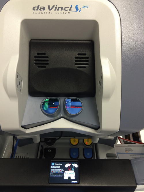
Fig. 3.2
Stereo viewer
The patient cart (Fig. 3.3) is the robotic component that interfaces with the patient directly. It consists of setup joints, which are used to position the arms. There are three instrument arms and one camera arm. The setup joints are connected to the camera and instrument arms, the camera arm holds and manipulates the camera, and the instrument arms do the same for the instruments. The camera arm is what provides the perfectly stable image. Each arm has its own clutch buttons that allow for movements of the arms during docking. Positioning the joints properly is essential to a procedure with the most intra-abdominal reach and the least arm collisions. In general the camera port, target anatomy, and center column of the patient cart should be placed in a straight line, such that the robotic arms are working toward the patient cart. The camera arm joints should be positioned such that the second camera arm joint is opposite arm number three. Also, the camera arm joints should be set up so that it is in its “sweet spot”; the sweet spot is indicated by a thick blue line on joint number two. The blue arrow should be within the boundaries of the thick blue line. This helps to insure that the patient cart is at an appropriate distance from the patient, which will improve arm mobility. Lastly, the camera port, target anatomy, camera port clutch button, third camera arm joint, and patient cart center column should be in a straight line. Exceptions to this exist when side docking; in this case, all other alignment remains true with the exception of the target anatomy which will be 30°–45° from the line created by the other points previously mentioned. The instrument arms should be placed at 45° angles to each other. If care is taken to establish ideal joint position, this will greatly impact on the seamlessness of the procedure. The movement of the patient cart is controlled with the shift switches and the motor drive control. The use of these components must be understood well by the surgeon and the nursing staff because it is essential to docking the robot properly. The patient cart is moved to the patient side using motor drive. This is accomplished by moving the shift switch into the drive position, indicated by the “D.” It is recommended that two people be used to move the cart, one to move it and one to direct that person. The throttle-enable switch is held in, and then the throttle is rotated away from you to move forward and toward you to move back. The cart can also be moved in neutral when the shift switch is in the neutral position indicated by the “N” and physically pushing the cart. The shift switch must be on “D” when docking is complete in order to set the breaks. Putting any port in a cannula mount will disable the motor drive and prevent the cart from moving in drive mode.
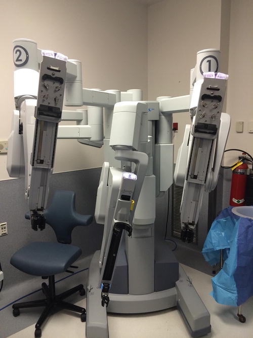
Fig. 3.3
Patient cart
The surgeon console is the surgeon’s interface with the da Vinci system; it also consists of many components. The stereo viewer provides the three-dimensional, high-definition video feed of the surgical field in real time. It also has a head and neck support for added ergonomic comfort. The stereo viewer also displays detailed messaging and icons that convey system settings for the surgeon during the procedure. These are displayed in specific locations throughout the procedure. The messages alert the surgeon to any changes or errors with the system. Next to the stereo viewer are infrared sensors that activate the surgeon console and robotic instruments when the surgeon’s head is against the stereo viewer; the instruments do not move when the head is removed. This prevents inadvertent movement of the instruments. The master controllers (Fig. 3.4) are where the surgeon places his fingers (Fig. 3.5) in order to control the instruments and the endoscope. The master controllers are the surgeon’s interface to the EndoWrist instruments, which afford 7 degrees of freedom, 180 degrees of articulation, and 540 degrees of rotation. The master controllers also provide ergonomic comfort and tremor filtration. Movements are simultaneously and seamlessly replicated at the patient cart. The master controllers also have a finger clutch option, which some surgeons prefer to the foot pedal master clutch. The finger clutch allows for clutching a single master controller without the other, unlike the master clutch foot pedal, which will allow for clutching of both master controllers. The da Vinci Si has 1.5 cubic feet of working space for the master controllers; the surgeon should use the master and finger clutches to establish a comfortable working environment and avoid collisions between the master controllers; this must be constantly adjusted throughout the procedure. The surgeon must also “match grips” by grasping the master controllers to match the position and grip of the EndoWrist instrument tips in the patient’s body. This prevents unwanted activation of the instruments and therefore tissue damage. It is advantageous to frequently clutch and keep the master controllers close, to avoid reaching for tissues and avoid surgeon strain. The left-side pod houses the ergonomic control lever; this allows one to adjust the height and tilt of the stereo viewer, move the arm rest up and down, and move the foot switch panel (Fig. 3.6) in and out; these are important for optimal comfort during the procedure. The right-side pod contains the power button and the emergency stop button. The power button will power on the surgeon console (Fig. 3.7) in standalone mode or when attached to the other system components can be used to power on the entire system. Pressing the emergency stop button will automatically stop system operation. The touch pad controls the system’s audio and video. It acts as the interface for the surgeon to adjust and save personal preferences. The foot switch panel houses the foot pedals. The pedals allow for arm swapping, master clutching, camera control, and integrated instrument activation control. The foot switches are where the actions of many instruments are executed; examples are the energy for monopolar instruments, bipolar instruments, vessel-sealing devices, and the stapler. The Si has two tiers of pedals and a pedal on the side of the panel. On the right side, there are two sets of cut and coagulation pedals, which can control two instruments. The pedal on the side of the panel is for arm switching, and the left-side pedals are for the camera and for master clutching.
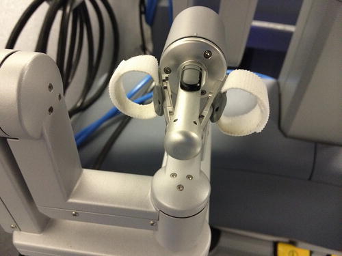
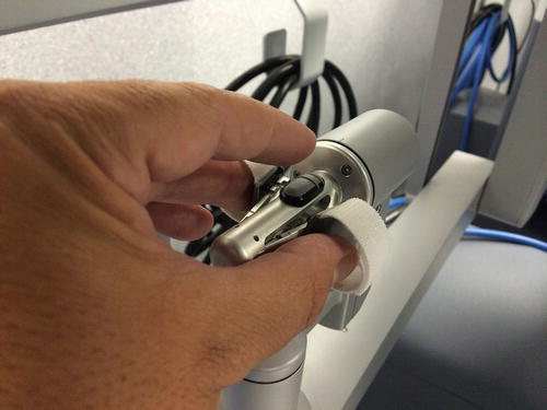
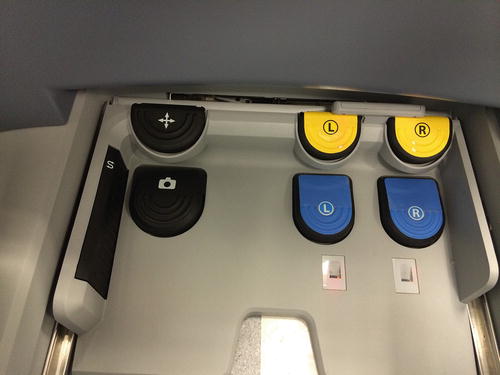
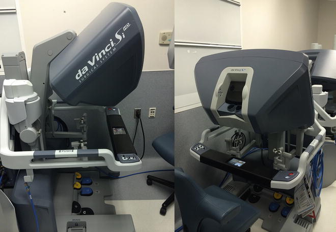
Fig. 3.4
Master controllers
Fig. 3.5
Master controller with surgeon
Fig. 3.6
Foot switch panel
Fig. 3.7
Surgeon console
There are many EndoWrist instruments available for the da Vinci; we will discuss those most commonly used in colorectal surgery. All instruments have a fixed number of uses; the system automatically tracks the number of uses and will not work if it has exceeded its maximum allowed uses. This information is relayed in the stereo viewer.
The monopolar curved scissors or “Hot Shears” can provide monopolar current. They function like laparoscopic endoshears with the added benefit of being wristed with the typical degrees of freedom described earlier. There are multiple graspers, scissors, and monopolar cautery devices; these are the most commonly used in colon and rectal surgery. The Hot Shears open to 38° and the jaws are 1.3-cm long. The permanent cautery hook is similar to the laparoscopic hook cautery, its hook is 1.6-cm long, and the permanent cautery spatula is 1.7-cm long. The Cadiere forceps are nontraumatic fenestrated graspers; they open 30°, and the jaws are 2.0-cm long; these are appropriate for handling bowel. The Double Fenestrated Grasper opens 60° and is 3.3-cm long; they have a very low closing force and can be used for bowel. The Fenestrated Bipolar Forceps open 45° and are 2.1-cm long and have a medium closing force, but allow for bipolar cautery; they are considered to be the bipolar equivalent to the Cadiere forceps. There are also Maryland Bipolar Forceps; they are curved and fenestrated, open 45° and are 2.1-cm long, and have a medium closing force.
With regard to needle drivers, there are five to choose from; two provide scissors at the base of the jaw. The Large Needle Driver and Large SutureCut are for midsize needles. The Mega Needle Driver and Mega SutureCut are for large needles. And the Black Diamond Micro Forceps are for small needles. All of the instruments mentioned thus far can be used up to ten times. There are also small, medium, and large EndoWrist clip appliers; they can each be used for up to 100 closures.
Related posts:


Stay updated, free articles. Join our Telegram channel

Full access? Get Clinical Tree


