Fig. 13.1
Fistula plug placement. The fistula tract is identified and curetted. A silk tie is then placed through the tract. The tie is then affixed to the fistula plug so that it will be pulled through the internal orifice out the external. The plug is trimmed for optimal passage. The plug is gently brought through the fistulous tract. The plug is sutured into place and the internal orifice is closed with figure-of-8 absorbable suture. The external end of the plug is trimmed to skin level for patient comfort. Images courtesy of Dr. Alex Ky
The following technique is provided by Gore Medical (Flagstaff, AZ) and comprises the corporate recommendations for procedure [13].
Preparation
Prepare the patient and surgical site using standard techniques appropriate for anal fistula repair.
Remove the device from its sterile packaging using aseptic technique.
Using sharp sterile scissors, trim the disk diameter to a size appropriate for the defect allowing for adequate fixation of the disk to the rectal mucosa. Care should be taken to avoid the creation of sharp edges or corners when trimming the disk.
Individual tubes can be removed from the device to accommodate the diameter of the fistula tract. When removing tubes, begin with the center-most tubes, carefully cutting the tube as close to the disk as possible (proximally adjacent) without compromising tube attachment.
To facilitate introduction and deployment of the device in the fistula tract, it is recommended that a suture be used to gather the tubes and pull the device through the fistula tract. To do so, run a suture through the distal ends of the tubes. A bite depth of approximately 3 mm is recommended to ensure adequate suture retention strength.
Note: The use of a resorbable suture is recommended to minimize the potential that any permanent material is implanted.
The GORE® BIO-A® Fistula Plug does not need to be hydrated prior to use. However, to facilitate passage of the tubes through the fistula tract, briefly immerse the entire device in sterile saline.
Device Placement
Use standard techniques to define, clean, and prepare the fistula tract. If necessary, the tract may be defined with a curette to remove any granulation tissue.
Insert a fistula probe or other suitable instrument through the fistula tract, entering through the external (secondary) opening and exiting via the internal (primary) opening.
Grasp the suture attached to the distal end of the GORE® BIO-A® Fistula Plug.
Gently draw the suture into the internal (primary) opening of the fistula tract. Continue to draw the suture through the fistula tract.
Once the suture is visible at the external (secondary) opening, slowly draw the GORE® BIO-A® Fistula Plug into the defect until slight resistance is felt and the device disk is securely seated at the internal (primary) opening.
Note: Take care to ensure that disk lies flat and is well apposed to the rectal mucosa at the internal (primary) opening of the fistula tract.
After the device is properly positioned in the fistula tract, one of the following fixation methods should be used to secure the disk at the internal (primary) opening.
Fixation Method I
Using a suitable resorbable suture, secure the disk of the GORE® BIO-A® Fistula Plug to the adjacent tissue, obtaining adequate bites of rectal wall to prevent device migration and minimize the potential for leakage of bowel contents into the fistula tract.
Fixation Method II
Using a suitable resorbable suture, close the rectal mucosa over the disk portion of the device to prevent device migration and minimize the potential for leakage of bowel contents into the fistula tract. Figures 13.2, 13.3, 13.4, 13.5, 13.6, 13.7, and 13.8 depict the set-up and installation of the fistula plug.
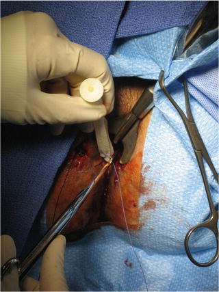
Fig. 13.2
The figure depicts fashioning disk and tube number to adequately close the fistula. Image courtesy of Dr. Alex Ky
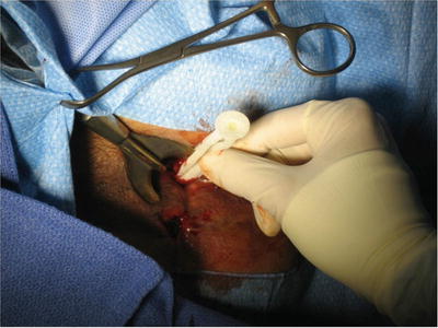
Fig. 13.3
The figure represents the fistula plug traversing the fistula from the internal to external opening. Images courtesy of Dr. Alex Ky
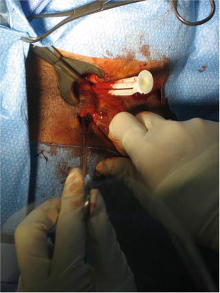
Fig. 13.4
The figure represents the fistula plug traversing the fistula from the internal to external opening. Images courtesy of Dr. Alex Ky
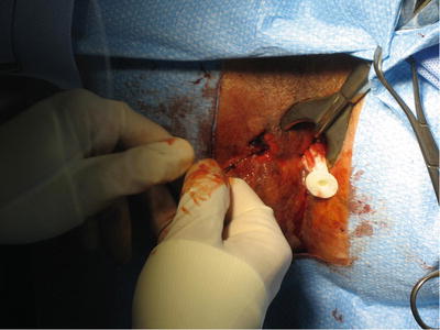
Fig. 13.5
The figure represents the fistula plug traversing the fistula from the internal to external opening. Images courtesy of Dr. Alex Ky
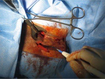
Fig. 13.6
The figure represents the fistula plug traversing the fistula from the internal to external opening. Images courtesy of Dr. Alex Ky
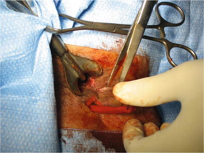
Fig. 13.7
The figure represents the fistula plug in its final position with the size of the external opening increased to allow for adequate drainage. Images courtesy of Dr. Alex Ky
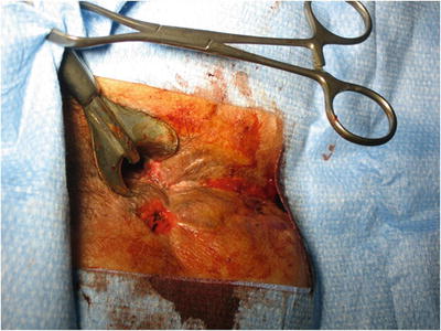
Fig. 13.8
The figure represents the fistula plug in its final position with the size of the external opening increased to allow for adequate drainage. Images courtesy of Dr. Alex Ky
Results
Buchberg et al. published a retrospective review of a prospectively maintained database between 2007 and 2009 comparing the Surgisis anal fistula plug to the Gore Bio-A fistula plug [14]. There were a total of 27 plug insertions over a 28-month period in 16 patients. Twelve patients underwent 16 Cook plug insertions and 10 patients underwent 11 Gore plug insertions. Several patients who initially failed the Cook plug were subsequently receiving Gore plugs.
Related posts:


Stay updated, free articles. Join our Telegram channel

Full access? Get Clinical Tree


