CHAPTER 4 Pressure/flow cystometry
AIMS OF PRESSURE/FLOW CYSTOMETRY
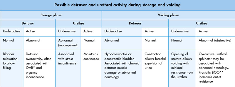
In addition, during cystometry it is possible to define the behaviour of the bladder during both the storage and voiding phases. In the normal situation the bladder fully relaxes during storage and contracts forcefully during voiding. Likewise it should be possible to define the behaviour of the urethra during both phases. Potential combinations of bladder and urethral function are reviewed in Table 4.1.
Pressure/flow studies also help characterize:
Pressure/flow cystometry techniques
Videocystometrography (VCMG; also known as videocystometry and video urodynamics)
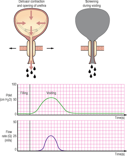
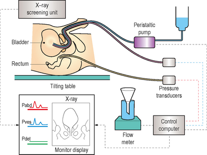
By combining subtraction cystometry with contrast media bladder filling and radiological screening it is possible to visualize the lower urinary tract during the storage and voiding phases. This results in the gold standard urodynamic investigation (Figure 4.1).
Radiological screening provides valuable additional anatomical information on:
Risks of pressure/flow studies
Subtraction cystometry or video urodynamics?
Many urodynamic units do not have the benefit of combined fluoroscopic screening and most patients can be adequately investigated using subtraction cystometry, particularly in the assessment of suspected detrusor overactivity. Suspected stress urinary incontinence is better assessed with video urodynamics, however it can still be evaluated during subtraction cystometry; albeit without radiological visualization of the leakage or an assessment of bladder base support and urethral mobility. Urethral pressure profilometry (Chapter 3) and leak point pressure measurements may provide additional information in stress incontinence when video urodynamics is not available, but their use is not standardized and remains controversial. Suspected BOO can also be diagnosed during subtraction cystometry but the addition of screening allows the level of the obstruction to be determined.
Terminology of pressure/flow cystometry
Some general terminology related to pressure measurements will be provided in table 4.2 for reference, additional terminology will also be included in the remainder of this chapter.
Table 4.2 Terminology relating to pressure/flow cystometry.
| Terminology relating to pressure/flow cystometry | ||
|---|---|---|
| Terminology | Definition or urodynamic meaning | Notes |
| Zero pressure | Should be the surrounding atmospheric pressure | Pressure recorded when the transducer is open to the environment |
| Reference height (level) | The level at which the transducers should be placed so that all urodynamic pressures have the same hydrostatic component | Taken at the upper edge of the symphysis pubis |
| Transducer | A device which converts pressure changes into an electrical signal | May be external to the patient or internally placed |
| Pressure | Force per unit area | Usually measured as cm H2O during urodynamics |
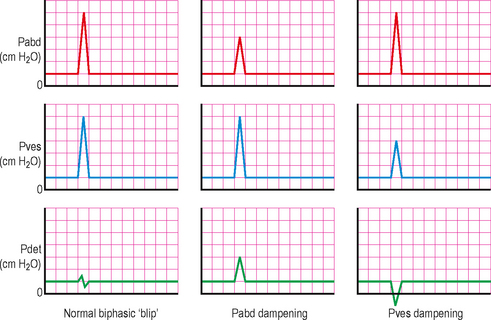
| Dampening | A specific type of artefact | Due to poor transmission of pressure to the transducer |
| Intra-vesical pressure | The pressure within the bladder | Abbreviated to Pves |
| Intra-abdominal pressure | Abbreviated to Pabd | |
| Detrusor pressure | The component of intra-vesical pressure created by forces in the bladder wall (the detrusor muscle) and calculated by subtracting intra-abdominal pressure from intra-vesical pressure | Abbreviated to Pdet (Pdet = Pves − Pabd) |
EQUIPMENT SETUP
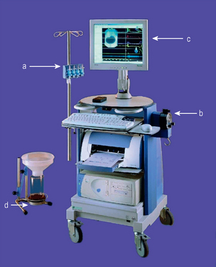
A typical fluid filled lines subtraction cystometry system requires the following components (Figure 4.2):
Measuring the pressures
Catheter placement
Intra-abdominal
The intra-abdominal pressure is also measured so that a detrusor pressure can be calculated using a computer. The measured intra-vesical pressure is composed of two components: the pressure created by the detrusor muscle, and also the pressure transmitted to the bladder from the external intra-abdominal pressure. By subtracting the intra-abdominal pressure from the intra-vesical pressure the pressure generated intrinsically within the bladder, i.e. from the detrusor muscle, is isolated. By and large the detrusor pressure is of greatest interest to the urodynamacist. The intra-abdominal pressure is usually measured by inserting a catheter into the rectum; however insertion into the upper vagina or into a stoma is also possible. The catheter usually has a flaccid, air-free balloon on the rectal end. The purpose of the balloon is to maintain a small fluid volume at the catheter opening and to avoid faecal blockage. The balloon should only be filled to 10–20% of its unstretched capacity and overfilling is a common mistake causing misleading measurements; often a slit is cut in the balloon to prevent overfilling and a tamponade effect. The rectal catheter should be inserted 10 cm above the anal verge using lubricant and taped securely as close to the anal verge as possible.
Transducers
Three types of transducer systems are in common usage.
External fluid charged pressure transducers
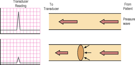
The ICS currently recommends use of external fluid pressure transducers due to their accuracy and inherent characteristics allowing easier use with regard to zero pressure and reference height (Figure 4.3). Urodynamics was originally developed using water filled systems and standardization has therefore developed from an understanding of the characteristics of fluid filled systems. The transducers are fixed externally on a stand and are connected via fluid filled lines to the pressure recording catheters. Fluid transmits the measured pressures directly to the external transducer and any interruption to the transmission of pressure waves may lead to artefacts. Common artefacts include an air bubble anywhere in the tubing between the tip of the catheter and the transducer; air is compressible unlike fluid and therefore a transmitted pressure wave will preferentially compress the air prior to reaching the transducer. The use of some of the pressure in compressing the air will result in a lesser wave being transmitted to the transducer resulting in ‘dampening’ of the trace (Figure 4.4). This is a common problem and even a miniscule air bubble can cause detectable dampening in the highly sensitive transducers. It can usually be rectified by flushing the air bubble out of the system. A fluid leak or a kink in the tubing will also have similar consequences, so it should be ensured that the system is water tight during the setup procedure and that there are no kinks anywhere along the tubing. Pressure sensing is point sensitive and therefore essentially unidirectional within the fluid filled system, albeit the pressure measurements are not so dependent on the orientation of the catheter within the bladder.
Catheter mounted transducers
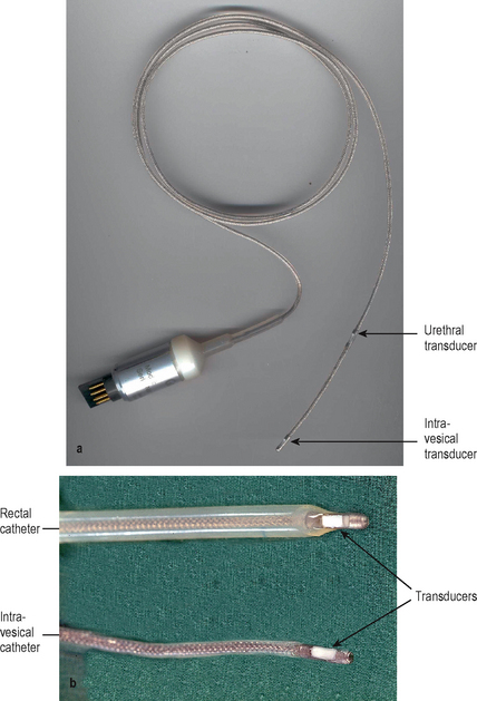
These transducers are mounted on the end of special (microtip) catheters. They do not require a fluid filled system and the external proximal end of the catheter is connected directly to the electronic recording system, thus making them simpler to setup than fluid filled systems (Figure 4.5). A reference height does not need to be setup for these systems and they are not affected by movement artefacts. They are therefore advantageous in certain situations such as ambulatory urodynamics, but for conventional cystometry they are not recommended by the ICS. The main disadvantage of this system is that the pressure readings are directional depending on which way the transducer is facing or what the transducer is lying against. Also they do need to be calibrated regularly before use. In addition the catheters are expensive and must be thoroughly cleaned before and after each usage and must be handled with care. Reference height unlike external fluid catheters is at the level of the internal transducer (see later). These catheters should be pre-soaked prior to usage to allow a small amount of water absorption into the coating on the sensing area. Cleaning/disinfecting using a liquid based method immediately prior to usage is sufficient pre-soaking. If not cleaned by a fluid method immediately prior to usage then approximately 20 minutes of pre-soaking is required if the catheter is used regularly; if the catheter has not be used for some weeks then pre-soaking for greater than 1 hour is required.
Air charged, pressure sensing technology
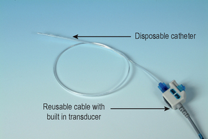
This is the newest transducer system. The system consists of reusable cables with built in transducers, and disposable catheters with a tiny balloon affixed on the distal end of the catheter (Figure 4.6). After the disposable catheter is inserted into the patient and connected to the permanent cable, the transducer is used to ‘charge’ the catheter by injecting a micro-volume of air into the catheter balloon. This creates a closed, pressure sensing system for accurate, in vivo recording of bladder, abdominal, and urethral pressures. This system is gaining popularity due to its simpler and quicker setup than fluid charged systems. In addition pressure sensing is not unidirectional and the catheters are disposable unlike with microtip catheters. The pressure measurement using the pressure sensing balloons is truly circumferential using this system unlike fluid filled and microtip systems and therefore may be of particular benefit when measuring urethral pressures, as the total pressure generated by the cylindrical urethral wall is measured. In addition these transducers are easily zeroed and similarly to microtip catheters the reference height does not need to be set externally but is taken at the point of the internal balloon. Dampening due to a change in the transmission medium (such as occurs when an air bubble is trapped in a fluid filled system) is not a problem in air charged pressure sensing catheters. The pressure measurements are also not influenced by any movements of the catheter, thus decreasing artefacts; this characteristic is ideal for ambulatory urodynamics. This technique does however need to be further studied before it can replace fluid filled catheters as the standard technique.
Filling the bladder
In addition to intra-vesical pressure measuring, the bladder also requires filling with fluid during pressure/flow cystometry (Figure 4.7).
Catheter types
Dual lumen
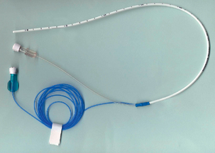
These are recommended by the ICS, since a single, dual lumen catheter can be used for both the intra-vesical pressure measurement and also for bladder filling (Figure 4.8). The thinnest possible catheter should be used to limit artefacts during voiding due to obstruction of the urethral lumen. However if too thin it may lead to excessive dampening of the pressure transmission and may also limit the pump rate. The smallest currently available size is 6 Fr, however such a small size is thought to limit the pump rate. In view of this a slightly larger size i.e. 8 Fr is probably preferable.
Quality control
Setting the zero pressure
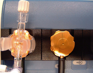
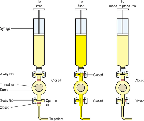
To zero to atmospheric pressure both the transducer measuring intra-vesical pressure and the transducer measuring intra-abdominal pressure must be opened to the atmosphere. This is easily facilitated if 3-way taps are incorporated into a fluid filled setup (Figure 4.9).
Setting the reference height
External fluid filled system
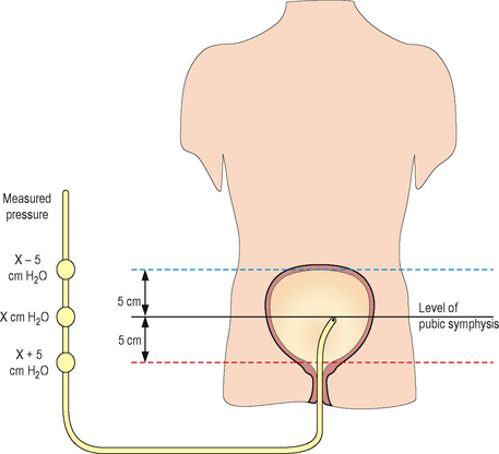
The reference height is the level at which the transducers must be placed so that all urodynamic pressures have the same hydrostatic component. To ensure standardization the ICS has defined the reference height as the superior edge of the symphysis pubis. The transducers are usually mounted on an adjustable stand and should be moved so they are level with the symphysis pubis prior to commencing the study (Figure 4.10).
URODYNAMICS IN PRACTICE – REFERENCE HEIGHT
Microtip and air filled systems
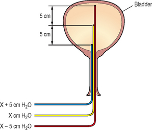
For microtip transducers the reference height is the transducer itself; for air filled transducers the reference height is at the position of the internal balloon. Using these systems it is therefore difficult to be certain of the position of the reference height or to ensure that the reference height of the intra-abdominal and the intra-vesical lines are equal, unless screening can show the position of the catheters (Figure 4.11). In addition alterations in the position of the patient (i.e. supine to standing) can cause significant differences in the relative positions of the intra-vesical and intra-abdominal transducers/balloons. In the supine position the rectal line is likely to be lower than the intra-vesical line, when standing the rectal line may be higher than the intra-vesical line. In practical terms these differences in height are unlikely to result in a significant effect on results.
Resting pressures
Prior to commencing bladder filling it is important to ensure that the initial values are in the expected range (Table 4.3). If the measured pressures lie outside of this range then this suggests a technical problem exists which needs to be rectified. Simple measures such as flushing the lines and checking for fluid leaks and kinks should be performed first.
Table 4.3 Expected resting range of intra-abdominal and intra-vesical pressures.
| Expected resting range of intra-abdominal and intra-vesical pressures | |
|---|---|
| Position | Expected range for intra-abdominal and intra-vesical resting measurements |
| Supine | 5–20 cm H2O |
| Sitting | 15–40 cm H2O |
| Standing | 30–50 cm H2O |
URODYNAMICS IN PRACTICE – TROUBLESHOOTING RESTING PRESSURES
 The Pabd may be too low – the rectal catheter may be kinked/blocked or may contain air bubbles or a fluid leak; therefore flush system, exclude leaks and kinks.
 The Pabd may be too high – the rectal catheter may have been misplaced, is resting against the rectal wall or the tubing may be kinked; therefore check position and exclude kinks. The rectal balloon may have a tamponade; therefore drain a few drops of fluid from the intra-abdominal measurement system or make a hole in the rectal balloon to remove excess fluid.
Dampening and subtraction
Having ensured that the resting values are as expected, any dampening must be identified and rectified. This is performed by asking the patient to cough; both the intra-abdominal and intra-vesical traces should respond equally with a rapid peak and a rapid drop and the detrusor trace should be unaffected. A small biphasic ‘blip’ is normal in the detrusor trace but any rise/fall in the detrusor pressure during the cough suggests dampening in either the intra-abdominal or the intra-vesical systems (Figure 4.12).
< div class='tao-gold-member'>
Stay updated, free articles. Join our Telegram channel

Full access? Get Clinical Tree


