(1)
Department of Vascular Surgery, Evangelisches Krankenhaus Königin Elisabeth Herzberge, Berlin, Germany
For the hemodynamic investigations we used two different methods: experimental flow investigations in a pulsatile flow system and numerical simulation. Experimental and numerical flow investigations are used when analytical and formula-based considerations alone do not lead to the solution of a flow-related problem. This also applies to the hemodynamic investigations presented here due to their complex geometries. The two methods do not compete but complement each other.
21.1 Experimental Flow Investigations
21.1.1 Creation of the Anastomotic Models for Flow Visualization
For the investigations, transparent silicone models were created using two different techniques.
1.
The first method involved a four step procedure:
(a)
Wax originals: Idealized original size models of the regions to be examined were created from dental wax. Liquid wax was poured into unilaterally-closed and fixated silicone pipes. After opening the pipes, the resulting wax rods were attached to each other using wires. We manually modeled the anastomotic regions.
(b)
Silicone molds (negative of the wax originals): The wax models served to form two-piece gray silicone molds. The wax originals were suspended in frames. Repeatedly applying a release agent, the molds were partially filled with silicone. After curing, the second half of the mold was finished.
(c)
Metal cast: A metal alloy (melting at 70 °C, bismuth-containing) was used for casting. Subsequent grinding and polishing yielded smooth surfaces, which did not impair the optical properties of the future silicone models.
(d)
Transparent silicone models: The metal blanks were fixed in another mold and covered with a release agent. All air inclusions were removed from the two components of the transparent silicone before the molds were cast. After curing, the metal alloy was removed by heating in a water bath.
2.
The second method began with the manual shaping of a metal model. Then the transparent silicone model was created. We used this method if only single models (instead of series) were needed. A detailed description of method 1 is listed in Huhle (2002) and Petzold (2001). Method 2 is described in Reddemann (2010).
21.1.2 Pulsatile Flow System
The pulsatile flow system that we developed is characterized by the maintenance of constant pressure irrespective of flow rate (Figs. 21.1 and 21.2). Two pressure reservoirs for the systolic (p syst) and diastolic (p diast) pressures, respectively, form its basis. The pressure for each is regulated separately within the range 0–290 mmHg. Two pressure-controlled peristaltic pumps operating at variable speeds filled the pressure reservoirs dependent on the total flow rate.
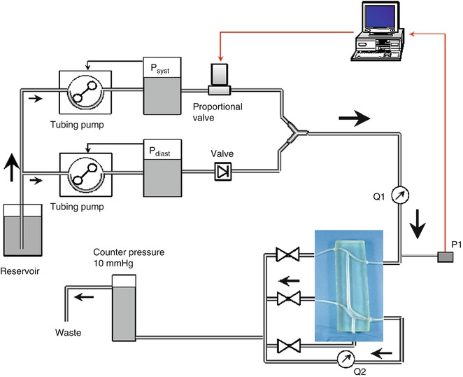
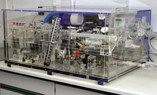
Fig. 21.1
Simplified pulsatile flow system. The video camera looked down at the model
Fig. 21.2
Pulsatile flow system
The diastolic pressure continuously prevailed at the outflow of the pulsatile flow system. During systole a solenoid valve opened and directed the systolic pressure to the outflow. This proportional valve, whose control voltage supply determined the displacement of a piston and thus the amplitude of the outflow pressure, was controlled by a personal computer. The typical pressure curve copied former intraoperative pressure readings, and was compared to the current pressure at the inflow of the model. This deviation generated the control signal. The diastolic reservoir was separated from the systolic pressure by a unidirectional valve. Corresponding to the constant preselected pulse rate of 60 min−1, the duration of each pulse cycle was 1 s.
Related posts:


Stay updated, free articles. Join our Telegram channel

Full access? Get Clinical Tree


