Magnetic Resonance Angiography in the Abdomen and Pelvis
Magnetic resonance angiography (MRA) has become an essential tool in abdominal and pelvic MR imaging (MRI). The utility of MRA has been enhanced by the addition of intravenous contrast agents and the recent proliferation of postprocessing techniques, many of which are largely automated and allow for real-time interaction on commercially available workstations. As a result, MRA examinations account for a significant percentage of the abdominal and pelvic MRI volume at many hospitals. At such centers, the volume of diagnostic catheter angiography performed has decreased proportionately.
MRA Techniques
Unlike conventional catheter-based angiography, MRA may be performed using a variety of techniques based on entirely different physical principles. Not every MRA technique yields equivalent results in similar situations. Therefore, it is important to understand the advantages and limitations of each technique. MRA techniques may be divided into two basic categories: non-contrast-enhanced and contrast-enhanced.
Non-Contrast-Enhanced Techniques
Dark Blood
The goal of dark blood angiography is to eliminate as much signal as possible from the blood vessels of interest. With most spin echo-based techniques (including fast spin echo and single-shot techniques), flowing blood results in a relative signal void on MR images. However, some signal often remains in the vessel lumen with these techniques if additional steps are not taken. A simple method of reducing intravascular signal on a dark blood sequence is to increase the echo time (TE). This allows more time for intravoxel dephasing and for blood excited by the initial 90-degree pulse to exit before experiencing the subsequent refocusing pulse. Gradient moment nulling is not used in this setting to allow dephasing caused by the imaging gradients to contribute to the signal loss from flowing blood. Placing a saturation band perpendicular to the vessel of interest upstream from the image slice can also reduce intraluminal signal.
Another technique for eliminating signal from vessels is called double inversion recovery. This technique uses slice-selective and non-slice-selective 180-degree inversion pre-pulses to eliminate signal from flowing blood. Stationary tissues experience both 180-degree pulses and begin the imaging cycle as if no pulses had been applied (the second inversion pulse reverses the effects of the first pulse). Blood flowing into the imaging plane only experiences the second 180-degree pulse and subsequently regrows longitudinal magnetization according to its T1 relaxation time. By beginning the imaging cycle at the null point of blood, the signal from flowing blood can be suppressed.
Dark blood techniques are useful for the depiction of intraluminal abnormalities such as dissection flaps and tumor thrombus (Fig. 2.1).
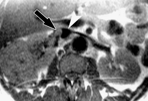 FIG. 2.1. Axial dark blood image performed at level of renal veins with double inversion recovery HASTE technique in patient with right renal cell carcinoma. Tumor thrombus (arrow) within inferior vena cava (arrowhead) is clearly depicted against signal void of flowing blood. |
Time-of-Flight
Time-of-flight MRA is based on the gradient echo pulse sequence and exploits the concept of flow-related enhancement to produce bright intraluminal signal. To minimize the effects of phase shifts experienced by moving protons (these phase shifts contribute to signal loss), flow compensation is used with time-of-flight imaging. Time-of-flight MRA can be performed with either a two-dimensional (2D) or three-dimensional (3D) acquisition. Typically, 2D acquisitions are preferred in the abdomen and pelvis to avoid saturation of blood that occurs when flowing blood remains in the imaging volume too long. In-plane saturation can be reduced for a 2D acquisition by choosing an imaging plane perpendicular to the flow within the vessel of interest. Arteries or veins can be selectively imaged with this technique by applying a
saturation band above or below the image slice. In this manner, blood flowing through the saturation band before entering the image slice loses signal, allowing display of unidirectional flow. In 2D acquisitions, saturation bands are most effective when traveling with or tracking the imaging slice (as opposed to remaining stationary while the imaging slice moves). Signal from any blood vessel passing through a saturation band is eliminated, regardless of whether it is arterial or venous. This can create a false impression of thrombosis within a target vessel with retrograde flow.
saturation band above or below the image slice. In this manner, blood flowing through the saturation band before entering the image slice loses signal, allowing display of unidirectional flow. In 2D acquisitions, saturation bands are most effective when traveling with or tracking the imaging slice (as opposed to remaining stationary while the imaging slice moves). Signal from any blood vessel passing through a saturation band is eliminated, regardless of whether it is arterial or venous. This can create a false impression of thrombosis within a target vessel with retrograde flow.
To allow for efficient imaging and better saturation of background tissues with time-of-flight MRA, the repetition time (TR) and TE are minimized, while the flip angle is kept between 30 and 60 degrees. Minimizing the TE also helps reduce the effects of dephasing (and resulting signal loss) due to complex flow. Cardiac gating may dramatically improve image quality for vessels with highly pulsatile flow (e.g., aorta and iliac vessels), but it significantly prolongs acquisition time (Fig. 2.2). Thin overlapping slices allow for more appealing 3D reconstructions. Time-of-flight MRA is seldom used to image the arterial system of the abdomen and pelvis, because it is time consuming and susceptible to artifacts. However, it remains useful for assessing the abdominal and pelvic veins.
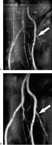 FIG. 2.2. Two-dimensional time-of-flight MRA (oblique maximum intensity projection) of pelvis showing benefit of cardiac gating. A: Ungated MRA demonstrates variable signal intensity of common and external iliac arteries. Internal iliac arteries (arrow) are poorly seen. Signal from veins eliminated by traveling inferior saturation band. B: Repeat study with cardiac gating demonstrates even distribution of high signal intensity throughout iliac arteries. Internal iliac arteries are clearly seen (arrow). Acquisition time for gated study exceeded 15 minutes, however. |
Phase-Contrast
Flowing protons develop a net phase accumulation relative to stationary tissues when a bipolar gradient (two gradients of equal strength but opposite polarity) is applied. This phase shift, which can be measured, forms the basis of phase-contrast angiography (the term contrast here refers to image contrast created by phase differences, not intravenous contrast material). Faster flowing protons experience a greater phase shift than slower moving protons, allowing for the
calculation of flow velocity. Therefore, phase-contrast MRA is inherently quantitative, unlike time-of-flight or gadolinium-enhanced MRA. The signal intensity of blood is proportional to its flow velocity in phase-contrast MRA, and the direction of flow can be determined based on the direction of the phase shift. However, flowing blood experiencing a phase shift in excess of 180-degrees is represented as flowing in the opposite direction (a phenomenon referred to as aliasing). Therefore, it is necessary to specify in advance the velocity of flow that is to be imaged by selecting the velocity-encoding parameter (frequently referred to as Venc). The velocity-encoding parameter determines the bipolar gradient strength, which in turn determines the flow velocity that results in a 180-degree phase shift. It is critical to estimate the velocity of flow in the vessel of interest with reasonable accuracy before the sequence is run (Fig. 2.3). In vessels for which the flow velocity is unknown, a series of 2D images performed while varying the velocity-encoding parameter can provide an estimated value. The velocity value for each axis or direction must be assigned separately, and for each flow direction encoded, the scan time is increased.
calculation of flow velocity. Therefore, phase-contrast MRA is inherently quantitative, unlike time-of-flight or gadolinium-enhanced MRA. The signal intensity of blood is proportional to its flow velocity in phase-contrast MRA, and the direction of flow can be determined based on the direction of the phase shift. However, flowing blood experiencing a phase shift in excess of 180-degrees is represented as flowing in the opposite direction (a phenomenon referred to as aliasing). Therefore, it is necessary to specify in advance the velocity of flow that is to be imaged by selecting the velocity-encoding parameter (frequently referred to as Venc). The velocity-encoding parameter determines the bipolar gradient strength, which in turn determines the flow velocity that results in a 180-degree phase shift. It is critical to estimate the velocity of flow in the vessel of interest with reasonable accuracy before the sequence is run (Fig. 2.3). In vessels for which the flow velocity is unknown, a series of 2D images performed while varying the velocity-encoding parameter can provide an estimated value. The velocity value for each axis or direction must be assigned separately, and for each flow direction encoded, the scan time is increased.
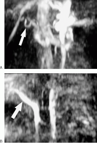 FIG. 2.3. Importance of proper velocity encoding for phase-contrast MRA. A: Three-dimensional phase-contrast MR portogram performed in patient without intravenous access using velocity-encoding of 25 cm/sec. Portal vein was poorly visualized and initially interpreted as thrombosed. Arrow denotes hepatic artery. B: Examination repeated later same day with velocity-encoding of 5 cm/sec demonstrates very slow portal flow (arrow). |
As with time-of-flight MRA, the signal from vessels can be selectively eliminated based on flow direction with the use of a saturation band. This may be unnecessary if the velocity-encoding parameter is appropriately selected, because the signal intensity of flowing blood is dependent upon its velocity. Phase-contrast technique is seldom used alone for abdominal and pelvic MRA, but it may be useful to confirm the significance of a stenosis identified using other techniques (see Fig. 1.53).
Additional Non-Contrast-Enhanced MRA Techniques
Newer methods of imaging blood vessels are continually being developed or refined. Balanced steady-state gradient echo sequences (TrueFISP, balanced FFE, FIESTA) have increased in popularity recently, due in part to their utility in cardiac imaging. The contrast mechanisms of these types of sequences are complex, demonstrating both bright blood and bright fluid (Fig. 2.4).
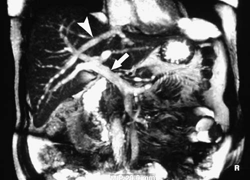 FIG. 2.4. Portal MR venogram performed with balanced-FFE sequence. Portal (arrow) and hepatic (arrowhead) veins are clearly demonstrated on this coronal maximum intensity projection image. This sequence required 20 seconds and no intravenous contrast. |
Contrast-Enhanced Techniques
Three-Dimensional Gadolinium-Enhanced MRA (CE-MRA)
The introduction of gadolinium chelates has dramatically expanded the clinical utility of MRA (Fig. 2.5). The basic sequence for contrast-enhanced MRA is 3D gradient echo. A 3D acquisition is preferable, because it allows for relatively thin contiguous image sections to be obtained during a single
breath-hold. Because this sequence relies on the T1 shortening effects of the gadolinium to enhance the target vasculature, saturation effects are not problematic like they are with time-of-flight techniques. In the typical 3D CE-MRA sequence, the TR and TE are minimized to allow for the most efficient imaging, while the flip angle is maintained at 30 to 60 degrees to allow for saturation of stationary tissues. This sequence closely resembles the 3D gradient echo sequence used for dynamic imaging of the liver, although the latter sequence uses a lower flip angle to prevent saturation of stationary tissues.
breath-hold. Because this sequence relies on the T1 shortening effects of the gadolinium to enhance the target vasculature, saturation effects are not problematic like they are with time-of-flight techniques. In the typical 3D CE-MRA sequence, the TR and TE are minimized to allow for the most efficient imaging, while the flip angle is maintained at 30 to 60 degrees to allow for saturation of stationary tissues. This sequence closely resembles the 3D gradient echo sequence used for dynamic imaging of the liver, although the latter sequence uses a lower flip angle to prevent saturation of stationary tissues.
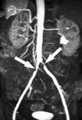 FIG. 2.5. Maximum intensity projection image of three-dimensional gadolinium-enhanced abdominal and pelvic MRA performed with 20 mL of contrast agent injected at 2 mL/sec via antecubital vein. Note bilateral iliac artery stenoses (arrows). |
Critical to CE-MRA is the ability to time the data acquisition to coincide with arrival of the contrast bolus in the vessel of interest. The dose of contrast necessary to perform abdominal and pelvic CE-MRA varies by scanner, target vessel, and operator confidence. We have found that most MRA examinations can be adequately performed with approximately 20 mL of gadolinium chelate. It is important to follow the contrast agent injection with approximately 15 to 20 mL of normal saline flush at the same injection rate to clear residual contrast material from the intravenous tubing and ensure adequate dose delivery.
Blood Pool Contrast Agents
Blood pool contrast agents have a prolonged intravascular phase, which means that a wide window of opportunity exists for imaging the blood vessels after contrast agent administration. However, imaging during the arterial phase is still necessary to avoid interference from venous structures. Blood pool contrast agents are not currently approved for routine clinical use at the time of this writing, and the utility of these agents for imaging the vessels of the abdomen and pelvis remains to be proven in clinical trials.
Methods of Background Suppression
Suppression of signal from nonvascular structures is usually desirable during MRA. Background tissue suppression typically occurs during MRA as the result of repeated radiofrequency (RF) pulses. By using a short TR and a sufficiently large (usually 30 to 60 degrees) flip angle, the longitudinal magnetization of the background tissues does not have sufficient time to recover between RF pulses and, therefore, becomes saturated. This alone often provides sufficient background suppression for diagnostic quality MRA. However, a variety of techniques may be used to further suppress background tissues.
Fat suppression and magnetization transfer are two easily performed techniques that must be selected before imaging. Magnetization transfer is used primarily for cerebral MRA, but fat suppression is commonly used in the abdomen and pelvis.
Another method of background suppression for CE-MRA involves image subtraction. With this technique, a precontrast scan (also known as a mask) is digitally subtracted from a postcontrast scan (Fig. 2.6). For this method to succeed, the two data sets must spatially match, because any movement between sequences results in spatial misregistration and poor image quality.
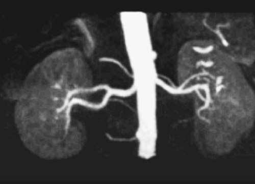 FIG. 2.6. Elimination of background signal. Renal artery MRA shows excellent visualization of renal arteries with minimal background signal. This was accomplished by subtracting precontrast data set from arterial phase data set and limiting thickness of reconstruction volume for this maximum intensity projection. |
Additional background suppression techniques are unnecessary with phase-contrast imaging, because stationary tissues accumulate no phase shift and are automatically subtracted to produce the angiographic images.
Timing of Contrast-Enhanced MRA
A properly timed CE-MRA sequence is one in which the portions of the acquisition related to image contrast (the center of k-space) are obtained when the contrast bolus is at peak concentration in the vessel of interest. If the image acquisition begins too soon, the critical image data are acquired before the contrast bolus peaks, causing a characteristic artifact (Fig. 2.7) (1). If the image acquisition begins too late, the vessel of interest is not maximally intense, and venous contamination may prevent optimal visualization of the arteries.
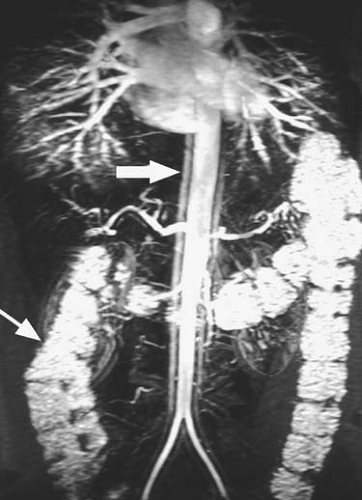 FIG. 2.7. Artifact from premature data acquisition during contrast-enhanced MRA. Centric ordered k-space acquisition initiated before contrast bolus peaked in aorta resulted in “ringing” artifact (arrow) on maximum intensity projection image. Note high signal intensity of colon contents (thin arrow), a common finding on three-dimensional MRA sequences that can be reduced through use of subtraction. |
Various methods exist to ensure proper timing of CE-MRA. To properly employ these methods, however, it is essential to know how the MRI system acquires data. In general, there are two widely available types of data acquisition used for CE-MRA. The standard type of acquisition is referred to as linear or sequential. In this situation, the data most responsible for image contrast (the critical data for CE-MRA) are acquired at the center of the acquisition. If a scanner uses this type of data acquisition, the scan must be timed so that the contrast bolus peaks near the center of the acquisition. In other words, if the acquisition is 20 seconds long, the contrast bolus should peak halfway through the acquisition, around 10 seconds into the scan. Therefore, a scanner acquiring data in a sequential manner should begin collecting data before the signal intensity peaks in the vessel of interest.
The other common method of data collection in CE-MRA is centric (also referred to as low-high, because the weakly phase-encoded echoes from the center of k-space are acquired first). In this instance, the data most responsible for image contrast are acquired near the beginning of the acquisition. One advantage of this technique is that the most critical data are acquired early, minimizing the effects of respiratory motion in patients who cannot tolerate a prolonged breath-hold. If the CE-MRA sequences of a scanner are centric ordered, the data acquisition should begin slightly later than with a sequential acquisition to ensure that the central lines of k-space are sampled when the contrast bolus is at peak concentration in the vessel of interest.
Timing Bolus/Test Injection
The time between injection of the contrast material and initiation of data acquisition is referred to as the scan delay. One method of determining the proper scan delay is with a timing bolus, which involves administering a bolus of 1 to 2 mL of gadolinium chelate while acquiring rapid sequential images of the vessel of interest. (Note: Follow the test dose with a bolus of approximately 15 to 20 mL of flush administered at the same injection rate as the test dose.) Imaging after the test injection is typically performed with a low spatial resolution 2D gradient echo sequence acquired at a rate of one image per second. This allows for determination of the time it takes from injection to peak concentration of contrast in the vessel of interest (referred to as the circulation time, bolus arrival time, or time-to-peak). This can then be entered into the following formula to obtain the scan delay for a sequential data acquisition:
Scan delay = bolus arrival time + [1/2 (duration of contrast injection) − 1/2 (scan acquisition time)]
For example, assume a renal MRA is being done in a patient in whom a bolus arrival time of 15 seconds, an acquisition time of 24 seconds, and injection duration of 10 seconds (2 mL/sec for 20 mL) has been determined. In this scenario, the scan should be initiated 8 seconds after the contrast delivery is started. Because the scan delay is calculated in advance, this technique has the benefit of allowing precise timing of the breath-hold. For most patients, the scan delay will be between 10 and 20 seconds, depending on cardiovascular status and site of injection.
The timing bolus method is best performed using the aorta as the reference vessel, because smaller vessels may not be well visualized with this technique. Flow-related enhancement in the aorta during the timing run may result in a periodic increase in signal intensity in the vessel of interest unrelated to the arrival of the contrast bolus. Therefore, any increased aortic signal intensity should persist for several seconds before being interpreted as the test bolus. Also, it is important to remember that the bolus arrival time refers to the time for the test injection to peak in the aorta, not the time to when it
is first visualized. For a centric ordered acquisition, the scan delay corresponds to the bolus arrival time.
is first visualized. For a centric ordered acquisition, the scan delay corresponds to the bolus arrival time.
Automatic Bolus Detection
Some scanners have software allowing the scan to be triggered automatically when the contrast bolus is detected (2). With this technique, the signal intensity is monitored within a region of interest placed over the abdominal aorta, or vessel of interest, following injection of the full diagnostic dose of contrast material. When the signal intensity exceeds a preset threshold value, data acquisition is triggered automatically. Because the scan delay is not known in advance, the patient must hold his or her breath quickly once the bolus is detected and the scan is triggered. Because the data acquisition begins when the contrast bolus is detected, a centric ordered acquisition should be used.
Real-Time Monitoring
Another method of timing the acquisition for CE-MRA involves real-time monitoring of the vessel of interest during injection of the full diagnostic dose of contrast material. With this technique, the technologist must coordinate monitoring the images for contrast arrival in the vessel of interest, initiation of patient breath-holding, and starting the scan. A delay of several seconds typically occurs between triggering the scan (i.e., pushing the button) and when the scan actually begins. This delay must be taken into account when timing the initiation of the scan.
Time-Resolved MRA
In some situations, it may be preferable to sacrifice spatial resolution for superior temporal resolution during the vascular phases of enhancement. This can be accomplished with a technique known as time resolved MRA (3,4,5). One approach to time-resolved imaging is simply to repeat the MRA sequence several times after the initiation of contrast material injection. The acquisition that best displays the vessels of interest is then used for image interpretation. With parallel imaging techniques (such as SENSE or SMASH), a complete MRA data set can be collected in a matter of seconds, and multiple data sets can be collected during a single breath-hold (Fig. 2.8). Alternatively, a dedicated time-resolved MRA sequence (such as TRICKS or Time-Resolved Imaging of Contrast Kinetics) can be used to collect data continuously after contrast injection during a single breath-hold. By alternating collection of the central and peripheral portions of k-space at several-second intervals, complete data sets can be reconstructed retrospectively with high temporal resolution. Future software and hardware innovations in this area will make time-resolved MRA commonplace, although few centers routinely use this technique currently.
Related posts:
 Basic Magnetic Resonance Imaging Principles for the Abdomen and Pelvis
 Magnetic Resonance Urography
 Magnetic Resonance Imaging of the Gastrointestinal Tract
 Modifying Sequence Parameters
 Glossary of Magnetic Resonance Imaging Terms
 What the Surgeon Needs to Know: Preoperative Assessment of Patients with Selected Tumors and Organ Transplant Candidates
Stay updated, free articles. Join our Telegram channel

Full access? Get Clinical Tree


