It has been said that exposure is key for open surgery. Similarly, the imaging platform used in endoscopic surgery, whether it is laparoscopic or robotic-assisted laparoscopic surgery, is a key for success. In this chapter, the history of laparoscope and imaging systems is reviewed. In addition, the difference between analog and digital image processing is explained. Three-dimensional imaging systems in addition to the da Vinci robotic system (Intuitive Surgical, Sunnyvale, Calif.) are described. Furthermore, advances in different scopes and cameras including high-definition (HD) and augmented reality (AR) imaging systems will be explained.
History of the Laparoscope
Surgical scopes are among the oldest surgical instruments. The first illuminated scope, dubbed the Lichtleiter or “Light Conductor,” consisted of a viewing tube, candle, and series of mirrors and was developed by Philipp Bozzini in 1804. Because of its impracticality, the device did not find favor among the surgeons of the day. However, it served as a source of inspiration to other inventors. Antonin Jean Desormeaux was the first urologist to view inside the bladder, in 1855. Using the principles of incandescent lighting, in 1867 Julius Bruck designed the first scope illuminated with an electrical light source. He used a platinum wire loop heated with electricity until it glowed. The main drawback to this design was the amount of heat generated by the light source, which could be conducted along the metal tubing of the scope to the tip. This heat represented a significant risk of burns to both the patient and the surgeon. In 1877, Maximilian Nitze used a lens system to widen the field of view (FOV) and succeeded in creating the first cystoscope as an instrument to visualize the urinary bladder through the urethra. The modern fiberoptic endoscope was invented by the British physicist Harold Hopkins in 1954. Hopkins used the term fiberscope to describe the bundle of glass or other transparent fibers used to transmit an image. The main advantage of the fiberscope was that the illumination source could be kept away from the scope with significant reduction in the amount of heat transmitted to the scope tip. However, the resolution of the fiberscope was limited by the number of fibers used. Therefore in the 1960s Hopkins invented the rod-lens system, which he patented in 1977. The rod-lens system used glass rods in place of air gaps, removing the need for lenses altogether, with resultant clarity and brightness that was up to 80 times greater than what was offered at the time ( Fig. 2-1 , top ). The rod-lens system remains the standard for currently used rigid endoscopes when high image resolution is required. Over time, with advances in fiberoptics and magnifying lenses, sophisticated surgical scopes evolved. In the next two sections, developments in scopes and cameras are detailed.

Scopes and Technology
Since the 1960s, the classic laparoscope has been composed of an outer ring of fiberoptics used to transmit light into the body, and an inner core of rod lenses through which the illuminated visual scene is relayed back to the eye piece ( Fig. 2-1 , top ). The different types of laparoscopes are defined in terms of the number of rods, size of laparoscope, and angle of view. With regard to size, laparoscopes are available in the range of 1.9 mm to 12 mm, but 5 mm is the most common size for pediatric patients, and 10 mm is the most common size for adults. Furthermore, viewing angles between 0 and 70 degrees are possible, with 0 and 30 degrees being the most commonly used ( Fig. 2-2 ). The 0-degree laparoscope offers a straight-on panoramic view. The 30-degree scope uses an angled lens, which can be used to view around corners, and can allow space for manipulation of laparoscopic instruments during surgery.

For a replication of the panoramic view of the human eye, which has a FOV of close to 180 degrees, the panomorph lens was recently developed. Whereas traditional laparoscopes offer less than a 70-degree FOV, the panomorph lens uses multivisualization software to widen the FOV to 180 degrees ( Fig. 2-3 ). However, the panomorph lens is not commercially available yet.

Further miniaturization of the charge-coupled device (CCD) chip technology and digital imaging allowed the CCD chip camera to be placed at the distal end of the endoscope; therefore the image is immediately captured by the CCD chip, digitized, and converted into an electrical signal for transmission. These systems, called digital video endoscopes, allow the signal to be transmitted directly to an image display unit with minimal loss of image quality and distortion, and without the need to attach the camera head to the eye piece of the scope or the fiberoptic cable for light source ( Fig. 2-1 , bottom ). Therefore, digital flexible cystoscopes, ureteroscopes, and laparoscopes with durable deflection mechanisms have been developed (e.g., EndoEYE, Olympus America, Melville, N.Y.) ( Fig. 2-4 ).

Cameras and Technology
Recent technologic advances—specifically improvements in how optical information is captured, transmitted, and produced as an image—have greatly enhanced laparoscopic surgery. Initially, an optical image is converted to an electronic signal that has information regarding both color and luminescence. This signal is then transmitted to a video monitor, where it is scanned to produce an image on the screen. The standard analog signal, in the form of the standard National Television Systems Committee (NTSC) video, uses a limited bandwidth that includes both color and luminescence information in a single or composite signal. There are many disadvantages to this system. First, processing of color and luminescence information separately and then combining both segments of information to create a video signal resulted in what is called signal noise or cross talk. This was accompanied by a decrease in resolution, grainy images, and loss of information around the edges of the video image. In addition, images and signals in the NTSC system are processed as voltage ( Fig. 2-5, A ). Therefore it is inevitable that small errors in recording and reproducing these voltages accumulate with each generation of video image. As a result, multiple copies of an analog image will reveal a decrease in quality of the video pictures.

Recently, digital imaging has revolutionized the process of image processing and display. A digital converter changes all video signals into precise numbers (i.e., 0 or 1) ( Fig. 2-5, B ). Once the video information has been digitized, it can be merged with other formats, such as audio or text data, and manipulated without any loss of information. This conversion to a digital signal prevents cross talk and image quality degradation. There are two formats of digital imaging. The first is called Y/C or super-video (S-video) , which allows the color and luminescence information to be carried as two separate signals with less cross talk, with cleaner and sharper images than those generated by composite signals. The second is known as the RGB (red-green-blue) format, which is also a component signal. The main difference from the Y/C format is that the video information (color and luminescence) is separated into four signals: red, green, blue, and a timing signal. In addition, each signal carries its own luminescence information, requiring four separate cables (red, green, blue, and sync). The separation of each video signal is performed electronically in the camera head. In contrast to the NTSC or Y/C format, the RGB format requires less electronic processing because the color and luminescence information are separate from the beginning. Therefore, RGB image quality is greatly enhanced when compared with the other two formats (NTSC and Y/C).
Analog medical cameras have been available since the mid-1970s; however, their use in operative applications was limited owing to their high weight and inability to be disinfected. Although the idea of coupling an endoscope with a camera was first described in 1957, it was impractical because cameras of the time were too large and cumbersome. The situation changed with the development of compact CCD cameras in the 1980s, when the endoscope could be coupled with CCD cameras and television (TV) monitors and the entire operating room team could watch the surgery. This allowed development of more complex laparoscopic instruments and procedures in which more than one hand is required to operate.
Based on a silicon chip called a charge-coupled device, the first solid-state digital camera was invented. It consisted of a silicon chip covered in image sensors, known as pixels. It converts the incoming light from a visual scene into a digital signal that can be stored, processed, or transmitted with greater efficiency and reliability than with an analog camera. In addition, digital cameras are lightweight, fully immersible, sterilizable, and shielded from electrical interference that may be created by cutting or coagulating currents during laparoscopic procedures.
A significant improvement in CCD camera technology has been the development of the three-chip camera, which contains three individual CCD chips for the primary colors (red, green, and blue) ( Fig. 2-6 ). Color separation is achieved with a prism system overlying the chips. This three-chip camera design produces less cross talk, with enhanced image resolution and improved color fidelity when compared with analog cameras. Further development in digital camera technology was the invention of a single monochrome CCD chip with alternating red, green, and blue illumination to form a color image, rather than with three chips that had three separate color filters. This design reduces the space requirements ( Fig. 2-6 ). Recently, complementary metal-oxide semiconductor (CMOS) technology has replaced CCD sensor technology in the industry of digital endoscopes, with superior image resolution, better contrast discrimination, lower power usage, cheaper cost, and 50% weight reduction.

The classic laparoscope does not have the ability to obtain high magnification and wide-angle images simultaneously. This represents a challenge when both close views and wide-angle images are required during sophisticated laparoscopic procedures. The reason is that when high magnification is required, a laparoscope is advanced closer to the organ. However, this results in loss of angle of view. Therefore a multiresolution foveated laparoscope (MRFL) was recently introduced. With two probes (a high-magnification probe and a wide-angle probe), an MRFL system can capture images with both high-magnification close-up and wide-angle views ( Figs. 2-7 and 2-8 ). At a working distance of 120 mm, the wide-angle probe provides surgical area coverage of 160 × 120 mm 2 with a resolution of 2.83l p/mm. Moreover, the high-magnification probe has a resolution of 6.35l pixel per millimeter (p/mm) and images a surgical area of 53 × 40 mm 2 . The advantage of the MRFL camera system is that both high-magnification images and a wide FOV can be simultaneously obtained without the need for moving the laparoscope in and out of the abdominal cavity, thus improving efficiency and maximizing safety by providing superior situational awareness. In addition, the MRFL system provides a large working space with fewer laparoscopic instrument collisions because the laparoscope is held farther away because of the magnification. In vivo evaluation verified the great potential of MRFL for incorporation into laparoscopic surgery with improved efficiency and safety. However, this system is still not commercially available.


During traditional laparoscopic surgery, an assistant is needed to control the laparoscope. Directing an assistant to control the camera can be challenging and may prolong the operative time. Therefore the earliest master-slave robotic surgical platforms controlled the laparoscope, freeing the surgeon to operate both hands and eliminating the need to rely on expert surgical assistants. Autonomous camera navigation systems have been invented to automatically keep surgical tools such as forceps and graspers in view. These systems use different methods for detecting operator intent and tracking the tool tips relative to the camera. These methods include “eye-gaze tracking,” “instrument tracking,” “kinematic tracking,” “image-based tracking,” “magnetic tracking system,” and “inertial measurement unit.” Recently, Weede and colleagues developed a test system that applies a Markov model to predict the motions of the tools so that the camera follows them. The system is trained with data from previous surgical interventions so that it can operate more like an expert laparoscope operator. Furthermore, Yu and colleagues proposed algorithms for determining how to move the laparoscope from one viewing location to another, using kinematic models of a robotic surgery system.
Another device that has been recently developed to overcome the camera handling difficulties during laparoscopic or robotic-assisted surgery is the RoboLens (Sina Robotics and Medical Innovators Co. Ltd., Tehran, Iran). It is a robotic system that uses an effective low-cost mechanism, with a minimum number of actuated degrees of freedom (DOFs), enabling spheric movement around a remote center of motion located at the insertion point of the laparoscopic stem. Hands-free operator interfaces were designed for user control, including a voice command recognition system and a smart six-button foot pedal ( Fig. 2-9 ). The operational and technical features of the RoboLens were evaluated during a laparoscopic cholecystectomy operation on human patients. RoboLens followed accurately the trajectory of instruments with a short response time.

Currently, laparoscopic endoscopic single-site (LESS) surgery is a further refinement of minimally invasive laparoscopic procedures. The main difficulty is the limited space for the laparoscope and other instruments. The miniature anchored robotic videoscope for expedited laparoscopy (MARVEL) is a wireless camera module (CM) that can be fixed under the abdominal wall to overcome crowding of instruments during LESS. The MARVEL system includes multiple CMs, a master control module (MCM), and a wireless human-machine interface (HMI). The multiple CMs feature a wirelessly controlled pan/tilt camera platform that enables a full hemispheric FOV inside the abdominal cavity, wirelessly adjustable focus, and a multiwavelength illumination control system. The MCM provides a near-zero latency video wireless communication, digital zoom, and independent wireless control for multiple MARVEL CMs. The HMI gives the surgeon full control over functionality of the CM. To insert and fix the MARVEL inside the abdominal cavity, the surgeon first inserts each CM into the end of a custom-designed insertion/removal tool ( Fig. 2-10 ). A coaxial needle is used to secure the CM during insertion and removal. The CM is secured to the abdominal wall without use of a separate videoscope for assistance. The surgeon can control the CM by a wireless joystick that controls the pan/tilt movement, illumination, adjustable focus, and digital zoom of all of the in vivo CMs. Each CM wirelessly sends its video stream to the MCM, which displays the images on high-resolution monitors.

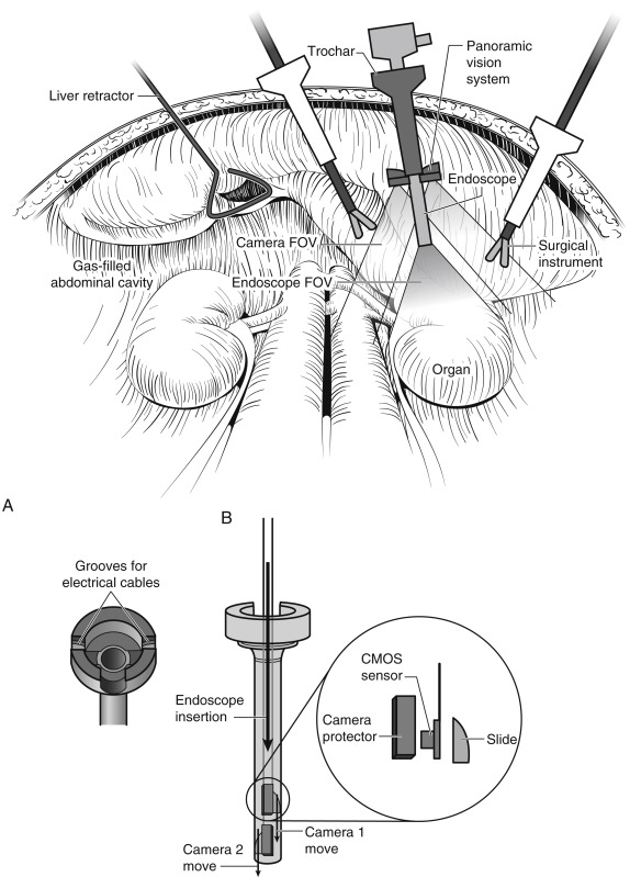
Most recently, Tamadazte and associates introduced their Multi-View Vision System. They tried to gather the advantages of stereovision, wide FOV, increased depth of vision, and low cost, without the need for either in situ registration between images or additional incisions. The system is based on two miniature high-resolution cameras positioned like a pair of glasses around the classic laparoscope ( Fig. 2-11 ). The cameras are based on two 5-mm × 5-mm × 3.8-mm CMOS sensors with a resolution of 1600 × 1200 pixels, a frame rate of 30 frames/sec, a low noise-to-signal ratio, an exposure control of +81 dB, an FOV of 51 degrees with a low TV distortion (≤1%). This device is not more invasive than standard endoscopy, because it is inserted through the laparoscope’s trocar.
Related posts:
 Laparoscopic and Percutaneous Delivery of Renal Ablative Technology
 Pyelolithotomy and Ureterolithotomy
 Laparoscopic Appendiceal Onlay Flap and Bowel Reconfiguration for Complex Ureteral Stricture Reconstruction
 Laparoscopic Live Donor Nephrectomy
 Robotic-Assisted and Laparoscopic Simple Prostatectomy
 Continent Urinary Diversion
Stay updated, free articles. Join our Telegram channel

Full access? Get Clinical Tree


