(1)
Department of Vascular Surgery, Evangelisches Krankenhaus Königin Elisabeth Herzberge, Berlin, Germany
AV accesses may cause insufficient perfusion of the extremity distal to the AV anastomosis as well as excessive cardiac strain. The therapy for both follows the same principles and is therefore discussed together.
11.1 Insufficient Peripheral Perfusion
If there are clinically relevant symptoms distal to the AV anastomosis due to an inadequate blood supply, we call this state insufficient peripheral perfusion.
11.1.1 Pathophysiology and Stages of Insufficient Perfusion
In the literature the inadequate blood supply to the extremity distal to the AV anastomosis is mostly called steal syndrome. In a true steal syndrome, however, there is usually a retrograde flow in the distal artery, which actually is not obligatory for insufficient peripheral perfusion. Therefore we do not use this expression. Figure 11.1 shows a drawing of the peripheral circulation of an extremity with the corresponding flow resistances. The venous outflow resistance R v is low unless there are hemodynamically relevant stenoses. Therefore it will be neglected in the following. Channeling flow portions from the proximal artery into the AV access leads to a decrease of pressure in the artery distal to the anastomosis (peripheral perfusion pressure p p). This pressure drop depends on:
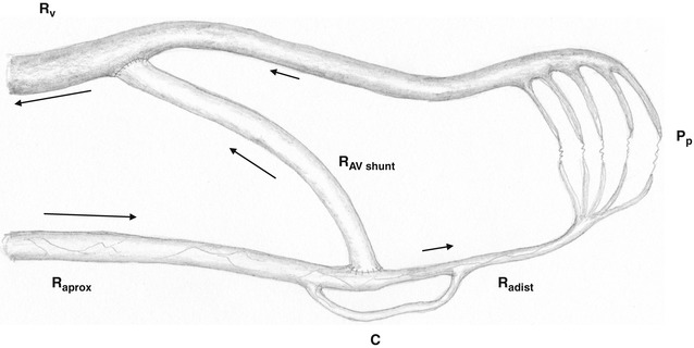
Fig. 11.1
Depiction of a peripheral circulatory segment with an AV shunt. R aprox inflow resistance, R adist peripheral resistance, R av resistance inside the AV shunt, R V central venous outflow resistance, P p peripheral perfusion pressure, C collateral
Resistance of the feeding artery (R aprox)
Resistance of the AV access (R av)
Resistance of the distal artery (R adist) and peripheral vasculature
Over the course of time these resistances may change.
The inflow resistance R aprox may decrease due to the dilation of the feeding artery.
The outflow resistance of the distal artery (R adist) may decrease due to the dilation of the peripheral vasculature.
Furthermore, collaterals, which can be quite pronounced between forearm and upper arm, must be taken into account. Anecdotal reports even mention cubital AV fistulas which are effectively fed by the distal stump of a proximally-occluded brachial artery without any signs of insufficient peripheral perfusion. Changing resistances may entail changes of the peripheral arterial perfusion pressure. After an initial pressure drop distal to the anastomosis, the following scenarios may develop (Fig. 11.2):
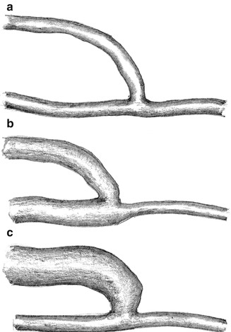
Fig. 11.2
Possible impact of an AV fistula on vascular morphology. (a) Absence of fistula dilation. (b) Dilation of the proximal artery. (c) Dilation of the vein
(a)
The initial peripheral pressure drop may persist, if the resistance of the feeding artery (R aprox) and the resistance of the AV access (R av) remain constant (neither dilation of the proximal artery nor of the AV access) (Fig. 11.2a).
(b)
The peripheral pressure increases due to the dilation of the proximal feeding artery (decrease of the inflow resistance R aprox) (Fig. 11.2b).
(c)
The peripheral resistance decreases continuously due to the dilation of the AV access (decrease of R av) (Fig. 11.2c).
Depending on resistance and collaterals, three different flow patterns in the AV anastomosis can be observed (Fig. 11.3):
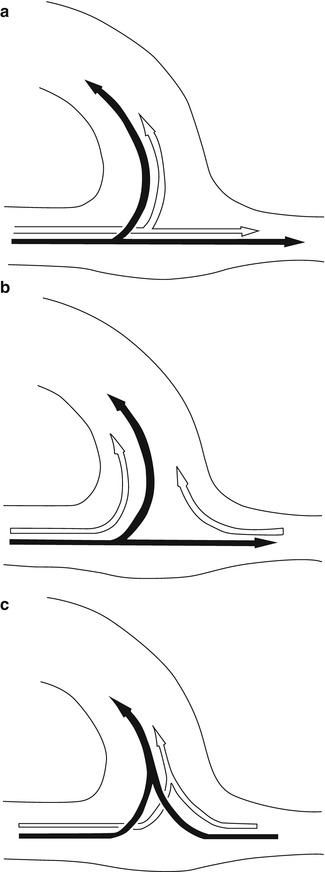
Fig. 11.3
Possible flow variants in the AV anastomosis (black arrows: systole, white arrows: diastole). (a) Systolic and diastolic inflow into the vein as well as into the distal artery. (b) Systolic inflow into the vein and the distal artery, diastolic (retrograde) inflow from the distal artery into the vein. (c) Systolic and diastolic inflow into the vein from the proximal as well as from the distal artery
(a)
Systolic and diastolic inflow both into the AV access as well as into the distal artery (Fig. 11.3a).
(b)
Systolic inflow both into the AV access as well as into the distal artery, and diastolic inflow into the AV access both from the proximal and distal artery (Fig. 11.3b).
(c)
Systolic and diastolic inflow into the AV access both from the proximal and distal artery (Fig. 11.3c).
The critical peripheral perfusion threshold – below which symptoms of insufficient perfusion occur – varies widely between individuals. Patients with high peripheral resistances such as diabetics suffering from small vessel disease are particularly prone to these complaints.
We distinguish between four stages of insufficient peripheral perfusion.
Stage I
Sensation of coldness and decrease in sensitivity in the affected extremity, particularly when exercising and during dialysis.
Stage II
Painful extremity particularly when exercising and during dialysis.
Stage III
Pain at rest.
Stage IV
Pain at rest and trophic disturbances possibly including tissue loss.
11.1.2 Vascular Investigations
The first step is to exclude a significant stenosis or occlusion of the feeding artery. Watch out for collateralized arterial occlusions. If there is a central stenosis or occlusion, it should be treated accordingly. Only with an unimpaired arterial inflow can the contribution of the AV access to the inadequate peripheral blood be evaluated. Apart from clinical examination, color duplex sonography is the primary diagnostic tool for measuring the flow in the AV access. As flow turbulence in the AV access may falsify the results, the flow should be determined in the proximal and distal feeding artery (Fig. 11.4). The flow direction of the distal artery should be noted (flow reversal with steal effect). The flow in the AV access (Q av) is
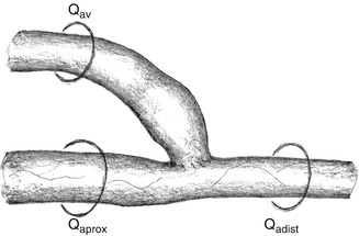
Fig. 11.4
Flow in the AV anastomosis. Q aprox flow in the proximal artery, Q adist flow in the distal artery, Q av flow in the AV shunt
As the flow in the AV access is proportionately related to the blood pressure, the systolic blood pressure also has to be recorded simultaneously. In many patients who need hemodialysis, blood pressure varies widely. The flow rate in the AV access at the lowest blood pressure is important (frequently occurring directly after dialysis).
11.1.3 Indications for Treatment
Perioperative complaints corresponding to stages I and II should be treated conservatively. Symptoms may be relieved by keeping the hand warm and moving it in warm water. The dilation of the feeding artery and other regulatory processes mostly lead to significant improvement. If symptoms do not get better after 3–4 weeks, we see an indication for reconstruction in stage II patients. In stage I it depends on the patient’s personal level of suffering and the complexity of potential procedures.
In stages III and IV we see principal indications for repair.
11.2 Therapy of Insufficient Peripheral Perfusion
Therapeutic Principles for Insufficient Peripheral Perfusion
1.
An AV access should only be ligated if all other means to improve the inadequate peripheral perfusion have failed. As a measure of last resort this is hardly ever necessary.
2.
It is highly likely that a new AV access in the same but contralateral position will lead to the same symptoms if all other conditions are equal.
Therapy aims at:
Permanent increase of the peripheral perfusion pressure to correct insufficient peripheral perfusion
Guaranteed preservation of the AV access
Prevention of irreversible vascular damage
The literature lists numerous methods, which basically boil down to two therapeutic approaches:
Flow reduction in the AV access
Proximalization of the arterial inflow into the AV access or of the stump of the distal artery
The approach that should be chosen depends exclusively on the flow rate in the AV access:
If the flow rate is higher than necessary for secure long term functioning, a flow reduction of the AV access is indicated.
If the flow in the AV access is around or slightly higher than the rate required for secure long term functioning, the proximalization of the arterial inflow is indicated.
To guarantee a reliable long term function and effective hemodialysis, in our view the flow rate should be at least:
Around 300 mL/min with AV fistulas
600–1,000 mL/min with ePTFE grafts (7 mm diameter)
In AV fistulas with extremely dilated veins, the necessary flow rate should be significantly higher.
The influence of flow reduction on peripheral perfusion cannot be exactly predicted. In some patients intraoperative flow and pressure readings distal to the anastomosis (in the cubital fossa) rise proportionally only above a certain systemic blood pressure threshold. In the rare cases when flow reduction does not suffice to raise peripheral perfusion pressure, proximalization should be carried out later. If even proximalization fails, the AV access should be abandoned possibly in favor of an arterioarterial graft. Figure 11.5 lists therapeutic options.
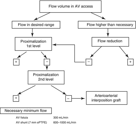
Fig. 11.5
Therapeutic strategy for insufficient peripheral perfusion
11.2.1 Flow Reduction
In the literature you can find numerous ways to reduce the flow with banding either involving circumscribed (ligature) or segmental (ribbon) narrowing of the lumen. Basically two aims should be achieved:
Precise reduction of the flow as desired
Stable long term results
Physical Principles
The impact of a stenosis on blood flow depends on diameter and length. To achieve the same flow reduction, a wide stenosis has to be significantly longer than a narrow one. The longer a stenosis that was created on purpose is, the more precisely it can be adjusted. At the same time this stenotic segment is no longer available for puncture. The smaller the diameter of a stenosis that has been created on purpose is, the shorter it needs to be. Yet it is more difficult to realize exactly the diameter that is required.
We examined transparent silicone models in a pulsatile flow system to determine the effects of the length and diameter of a narrow segment on the extent of flow reduction. In this system the narrow segment was interspersed between a 6-mm artery and a 7-mm graft.
For better illustration, Fig. 11.6 shows narrow segments of different diameters (1.2, 3, and 4 mm, respectively) in scale as well as the different lengths that are required to reduce the flow by 40 %. The results were found in our pulsatile flow system (Chap. 21). The inflow through a 6-mm fake artery into the 7-mm fake AV graft (pipe) met the counter pressure of a 12-cm water column (venous outflow). For the 4-mm narrow segment we investigated lengths of up to 70 mm. This length resulted in a flow reduction of only 28 %. Its length (150 mm) required for the 40 % flow reduction shown in Fig. 11.6 was determined approximately by the Hagen–Poiseuille equation.
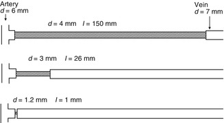
Fig. 11.6
Exemplary calculations to achieve a 40 % flow reduction via a narrow segment with diameters of 6 mm for the artery and 7 mm for the vein. Appropriate length/diameter combinations of the narrow segments would be 150/4, 26/3, and 1.2/1 mm
Already discrete variations in diameter of small caliber narrow segments lead to considerable flow changes. A different flow velocity in the stenotic segment has important implications in a biological system. The narrower the stenosis, the higher the flow velocity and the mechanical irritation at the vascular wall. Clinical experience shows that with very small diameters there is an elevated risk of tissue proliferation and occlusion of the lumen.
Therefore it is important to find a compromise between:
The precise extent of the stenosis you want to create surgically.
The partial loss of the segment that is suitable for puncturing because a narrow segment is not suited for needle placement.
Experiments on the Influence of Diameter and Length of a Narrow Segment on Shunt Flow in the Pulsatile Flow System
For these investigations we created precision acrylic glass models (Figs. 11.7 and 11.8). The diameters of the model arteries varied between 2 and 7 mm, and the lengths of the narrow segment between 0 and 70 mm.
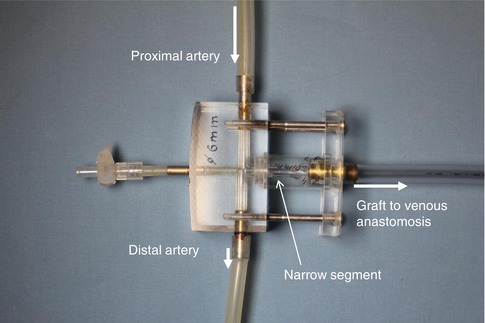
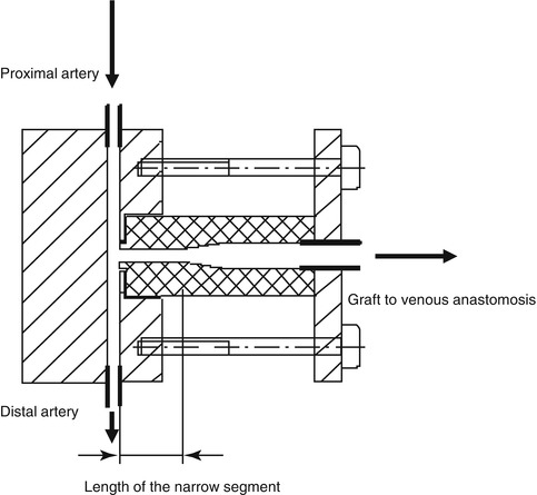
Fig. 11.7
Model of the arterial anastomosis with narrow segment. The other end of the prosthetic graft is connected to the venous model anastomosis (see Fig. 4.7)
Fig. 11.8
Model of a narrow segment. Cylinders with different diameters and lengths are mounted to the model’s artery as narrow segments
Figure 11.9 shows the relative flow reduction with 4-mm narrow segments upstream from the prosthesis at an arterial pressure of 100 mmHg. Here the results are normalized to flow rates without a narrow segment (direct anastomosis of the graft).
Fig. 11.9
Relative flow reduction by a 4 mm diameter narrow segment dependent on its length and the arterial diameter (2–7 mm)
The relative flow rate decreases with an increasing diameter of the artery. Likewise, the same is true for an increasing length of the narrow segment. As an example the 70 mm long narrow segment (7 mm diameter) reduces the flow by 5 % if anastomosed to a 2 mm diameter artery and by 28 % if anastomosed to a 7 mm diameter artery (Krueger et al. 2001, 2004; Zanow et al. 2006a, b).
If the diameter of the narrow segment is only 3 mm, the impact on flow reduction is much more pronounced (Fig. 11.10). Under these circumstances the flow reduction may be as high as 55 % (7 mm diameter artery, length of narrow segment 70 mm). The flow reduction after only 5 mm is already so pronounced that it would be difficult to achieve a flow reduction precisely as desired in a real life situation in the operating room with such a short segment.
Fig. 11.10
Relative flow reduction by 3 mm diameter narrow segments of different lengths. Parameter: arterial diameter
The higher the inflow resistance is (narrow native artery), the less influence an intercalated narrow segment has on flow reduction. The lower the inflow resistance is (wide native artery), the more influence an intercalated narrow segment has on flow reduction.
Surgical Technique
Our technique involves the controlled, long segment narrowing of an AV access near the arterial anastomosis. We perform two variants:
The narrowing of the AV access close to the anastomosis by a running suture.
The interposition of a specially designed narrow prosthetic segment.
Technical Hint
If the anastomosis is close to the cubital fossa, there is a definite risk of kinking of the narrow segment when the elbow is flexed. Taking into account individual topographic conditions, preoperative planning includes the decision whether flow reduction is performed:
In the region of a preexisting anastomosis, or
After surgical closure of the pre-existing anastomosis further proximal to the cubital fossa with a then newly created anastomosis.
Flow Reduction by a Long Running Suture
From 1982 through February 2009 we performed this technique in around 450 patients who mainly had AV fistulas. Frequently, close to the anastomosis their veins were considerably dilated, and sometimes even to an extreme extent. Also, due to their lengthening, these veins followed meandering circuitous courses. If this morphology was present, surgery followed a six-step procedure.
Exposure
Circumferential exposure of the vein near the anastomosis, of the anastomoses, and of the artery proximal and distal to the anastomosis (Fig. 11.11). Should the exposure of the distal artery prove very cumbersome, it may be abandoned.
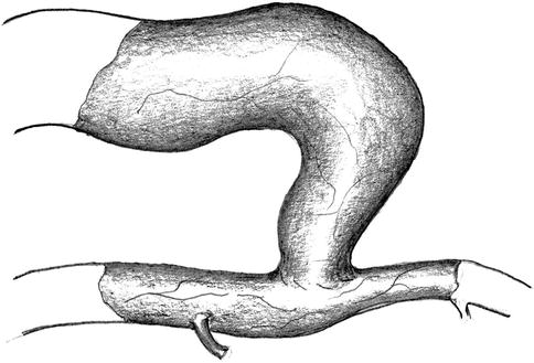
Fig. 11.11
Isolation of the artery and vein near the anastomosis
Shortening of the Vein
Separation of the vein from the anastomotic orifice for adequate shortening (Fig. 11.12).
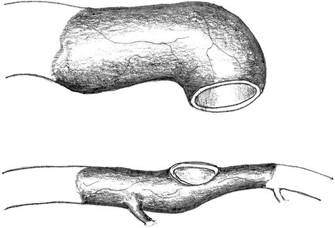
Fig. 11.12
Disconnection of the anastomosis
Plasty of the Vein Stump
The planned running suture for the defined narrowing of the vein may only be performed in a vein whose lumen has already been reduced to 5–6 mm. For this purpose it is necessary to excise a triangular portion of the venous wall over a distance of 3–5 cm (Fig. 11.13) so as to create a funnel-like narrower lumen by a running suture (Fig. 11.14).
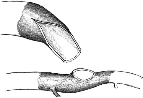
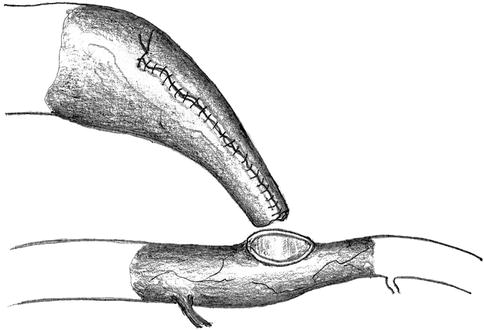
Fig. 11.13
Resection of a triangular wall portion to reduce the lumen
Fig. 11.14
Creation of a new lumen by suturing the wall margins
Reanastomosis
The anastomotic orifice of the artery is frequently wider than the lumen of the prenarrowed vein. It is also easy to narrow the orifice using a running suture. After an adequate diameter has been created, the next step is to suture the lateroterminal anastomosis (Fig. 11.15).
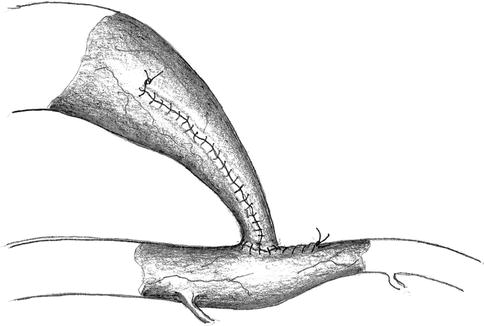
Fig. 11.15
Narrowing of the arteriotomy and reanastomosis with the venous stump
Controlled Flow Reduction
The plasty of a vein to reduce its diameter to 5–6 mm most often does not lower the flow rate sufficiently by itself. Therefore we continue with a running (6-0) suture of the vascular wall over a 2–3-cm segment under constant monitoring of the blood flow. A stepwise approach with several rows of sutures upon each other yields the desired effect. The intended newly-created stenosis takes on a concave form (Fig. 11.16). When fine-tuning the flow rate, you should also watch the current arterial blood pressure so as to make adjustments for anesthesia-related differences from normal readings in each individual patient.
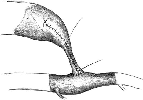
Fig. 11.16
Narrowing of the venous lumen using a running suture while measuring the flow
We measure the intraoperative flow by the sonographic transit-time method only. For best results use both the proximal and distal artery. Thus you can determine the flow rate in the AV access when taking into account the flow direction in the distal artery. According to our experience, the direct sonographic examination of the AV access is error-prone.
Wrapping of the Narrowed Segment
The vascular wall of the narrowed segment consists of a formerly (possibly extremely) dilated vein. We have seen secondary dilatations with subsequent increases in blood flow. To avoid this dilatation we wrap an ePTFE or polyurethane cuff around the narrowed segment and secure it with a running suture (Fig. 11.17). If this suture is too loose, dilation will occur anyway. If it is too tight, an additional unwanted flow reduction will arise. Therefore another control is necessary to verify the desired result. If the surgical field is in the cubital fossa, flow should also be checked during elbow flexion.
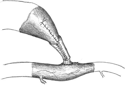
Fig. 11.17
Wrapping the narrow segment with an alloplastic cuff
Figure 11.18 shows an example of intraoperative flow rates in the arterialized cephalic vein of the upper arm and the pressure in the distal artery before and after flow reduction.
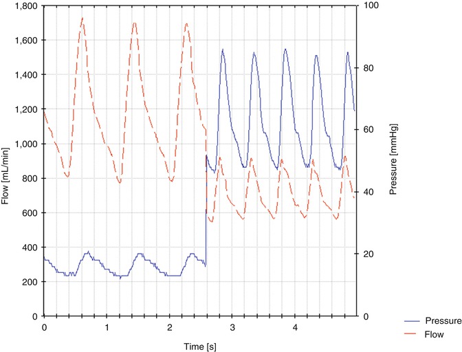
Fig. 11.18
Examples for pressure and flow curves before and after flow reductions. The mean pressure in the anastomosis rises from 16 to 63 mmHg. The mean flow drops from 1,170 to 700 mL/min
Clinical Results
In 453 flow reductions (February 1981 through February 2009) we observed the results and complications detailed below within the first 12 months (no consistent follow up after the second postoperative week).
Related posts:


Stay updated, free articles. Join our Telegram channel

Full access? Get Clinical Tree


