Fig. 4.1
RoboSurgeon system. Three dimensional (3D)
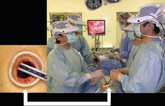
Fig. 4.2
A port and 3D head-mounted display that all surgeons wear. Scrub nurse (SN)
With the two-port access technique, the kidney and proximal ureter are isolated through an ipsilateral flank port (the upper port) and the distal ureter with bladder cuff via an ipsilateral lower abdominal pararectal port (the lower port). This technique is, in other words, a combination of two single-port surgeries.
The RoboSurgeon system consists of three components: a three-dimensional (3D) head-mounted display (3D-HMD), handheld robot-like devices, and an endoscope manipulation robot (Fig. 4.1). Depending on the situation, part or all of this system is used, but the 3D-HMD, which provides six fields of vision, is always used by surgeons.
This surgery achieves four key “no’s”: no high costs, no CO2, no multiple ports, and no intraperitoneal injury. The adjustable size of the port ensures safety and makes it easy to learn this procedure (Fig. 4.3). Prophylactic antimicrobial agents are unnecessary in the perioperative period [8–12].
Fig. 4.3
Fundamental concept of gasless single-port RoboSurgeon surgery
Without the RoboSurgeon system, gasless two-port-like surgery in which the port size is somewhat larger can be performed following the procedures presented here using a system with an ordinary two-dimensional endoscope and display [13, 14].
This surgery may help overcome some of the disadvantages of current laparoscopic and robot-assisted minimally invasive surgeries while retaining their major benefits and adding some unique advantages [4, 5].
4.2 General Concept
This surgery is carried out in a wide retroperitoneal working space made along the anatomical plane through two, coin-sized single ports, without gas insufflation, and assisted by the RoboSurgeon system that consists of wearable or head movement-controlled devices. For more details, see Chap. 1, Fundamentals of Gasless Single-Port RoboSurgeon Surgery.
4.3 Preoperative Preparation
Patients are provided with sufficient information, including the potential need to extend the port size in the event of difficulties, when obtaining informed consent. Patients do not receive prophylactic antimicrobial agents in the perioperative period at our hospital [12].
4.4 Instruments
This operation can be performed with reusable and affordable devices. Disposable devices, a vessel sealing device and an ultrasonic coagulator, are usually used but can be replaced with reusable ligation devices and scissors. A catcher to remove the specimen is the only disposable (but affordable) device that is not replaceable. The endoscope manipulation robot that works with air pressure (Aerovision® [initial version], EMARO® [second version], Riverfield, Inc.) can also be replaced by an endoscopist. See Chap. 1 for details.
4.5 Surgical Techniques
4.5.1 Principles
All surgeons put on the 3D-HMD and obtain images in the following manner (Figs. 4.4, 4.5, 4.6, and 4.7). During the operation, the 3D-HMD provides the following six fields of vision in front of the eyes regardless of head position: magnified vision, stereovision, panoramic vision (direct vision), multivision, navigated vision, and shared vision. Using the direct vision obtained by moving the angle of sight downwards, surgeons can receive instruments from the scrub nurse and can also observe the operative field to ensure safety. Through a port, the surgeon initially inserts the instruments, including the endoscope, using direct vision and then follows them on the 3D-HMD. Each surgeon can change the direction of the images on the 3D-HMD according to his or her position, which makes it possible to share a common direction. Multivision, including navigated vision using ultrasonography via the port, can be employed if necessary.
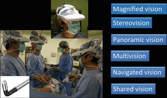
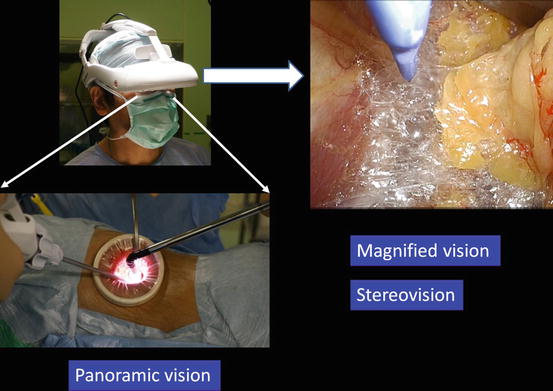
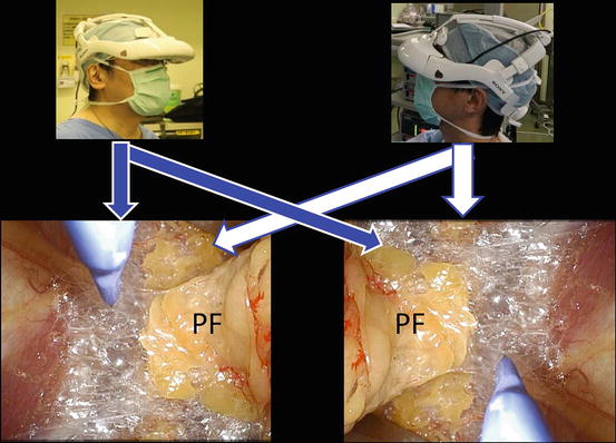
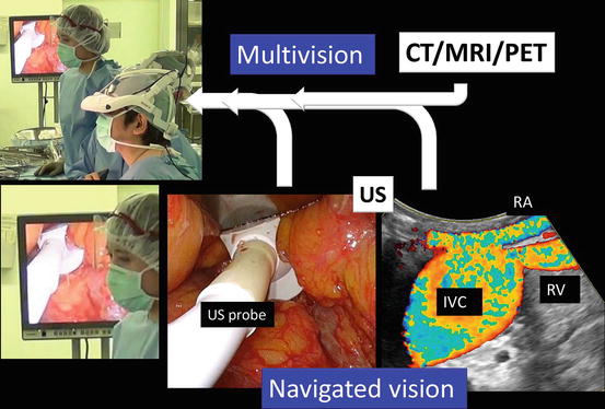
Fig. 4.4
3D-HMD provides six fields of vision in front of the eyes regardless of head position
Fig. 4.5
Magnified vision, stereovision, and panoramic vision are obtained. A wide panoramic view can be seen by moving the angle of sight downwards
Fig. 4.6
Each surgeon can change the direction of the images on the display according to his or her position
Fig. 4.7
Multivision and navigated vision using ultrasonography via the port. Computerized tomography (CT), magnetic resonance imaging (MRI), positron emission tomography (PET), ultrasound (US), renal artery (RA), renal vein (RV), inferior vena cava (IVC)
A wide retroperitoneal working space for isolation of the kidney and the upper ureter is made through the upper port by dissecting the steric connective tissue along the anatomical plane between the perinephric fat and the psoas muscles posteriorly and between the perinephric fat and the peritoneum anteriorly (Figs. 4.8, 4.9, and 4.10). The working space for isolation of the lower ureter with bladder cuff is made through the lower port by dissecting along the steric connective tissue between the bladder and the pelvic wall (Figs. 4.8, 4.9, and 4.11). The following procedures are performed in the wide working space developed in the retroperitoneum.
Fig. 4.8
Retroperitoneal working space made along the anatomical plane through a port
Fig. 4.9
Retroperitoneal working space made through the upper and lower ports, a combination of two single-port surgeries. Through the upper port, the kidney and proximal ureter are isolated, and through the lower port, the distal ureter with bladder cuff is isolated
Fig. 4.10
Detailed image of the working space made through the upper port. Adrenal gland (AG), perinephric fat (PF)
Fig. 4.11
Detailed image of the working space made through the lower port
Representative scenes of extraction of the kidney and ureter with bladder cuff through the upper port, which permits narrow extraction of the specimen, are presented in Fig. 4.12.
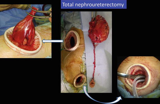
Fig. 4.12
Extraction of the kidney and ureter with bladder cuff en bloc through the upper port and insertion of drainage tubes through the lower port
4.5.2 Flowchart of the Procedures
All procedures are performed extraperitoneally. An overview of the procedures is shown in Fig. 4.13. First, the kidney and proximal ureter are isolated through the ipsilateral upper port. Consequently, the table is rotated to a semioblique position, and the distal ureter with bladder cuff is isolated through the ipsilateral lower port. The specimen is then extracted through the upper port en bloc, and the lower port is used for drainage.
Fig. 4.13
Overview of procedures
4.5.3 Procedures via the Upper Port
4.5.3.1 Patient Positioning
After general anesthesia is administered, the patient is placed in the flank position over the break of the table (Fig. 4.15). The supine position is employed for patients with poor cardiopulmonary function; for those with severe osteoporosis, when the transumbilical single-port approach for improved cosmetic results is utilized; etc. Surgeons put on the 3D-HMD and stand by the table as shown in Fig. 4.16. The lead surgeon stands at the dorsal side of the patient. An endoscopist (or an endoscope manipulation robot) and an assistant are located opposite the lead surgeon. The direction of the images on the lead surgeon’s 3D-HMD is reversed from those of the endoscopist/robot.
Fig. 4.15
Patient position
Fig. 4.16
(a) Surgeon’s position. (b) Surgical hand washing
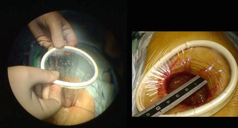
4.5.3.2 Port Placement
A skin incision is made, usually around 3–4 cm in length so as to permit narrow extraction of the specimen, starting at the tip of the 12th rib and running obliquely forward following the line of the 12th rib (Fig. 4.17). The incision is extended as needed when the specimen is extracted. Muscles are split, and the tip of the 12th rib is slightly shaved if necessary. The flank pad and the lateroconal fascia are exposed (Fig. 4.18), and the fascia is opened to expose the posterior aspect of Gerota’s fascia (Fig. 4.19). The posterior aspect of Gerota’s fascia is bluntly pushed medially using a long retractor (PLES retractor®, Innomedics Medical Instruments, Inc.), and the ureter is identified immediately. After separating the anterior aspect of Gerota’s fascia to some extent from the peritoneum (Fig. 4.18), a wound retractor (Alexis wound retractor®, Applied Medical Resources, Corp.) is placed along Gerota’s fascia to make the upper port (Fig. 4.20).
 < div class='tao-gold-member'>
 Gasless Single-Port RoboSurgeon Retroperitoneoscopic Pelvic Lymph Node Dissection and Inguinal Hernia Prevention
 Gasless Single-Port RoboSurgeon Partial Cystectomy: A Hybrid Technique Combining an Intravesical and Extravesical Approach
 Gasless Single-Port RoboSurgeon Retroperitoneoscopic Radical Prostatectomy
 Gasless Single-Port RoboSurgeon Retroperitoneoscopic Radical Nephrectomy
 Gasless Single-Port RoboSurgeon Retroperitoneoscopic Adrenalectomy
 Fundamentals of Gasless Single-Port RoboSurgeon Surgery


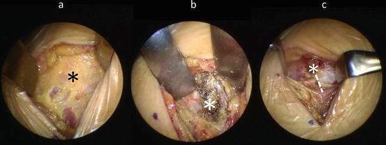
Fig. 4.17
(a) Skin incision, (b) identification of the tip of the 12th rib (*), and (c) shaved tip. The dotted line is opened to expose the flank pad
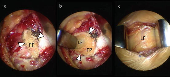
Fig. 4.18
(a–c) Exposing the flank pad (FP) and lateroconal fascia (LF). Edge of the opened fascia (arrowhead)
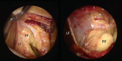
Fig. 4.19
Opening the lateroconal fascia (LF) to expose the perinephric fat (PF) covered with Gerota’s fascia (GF)
Only gold members can continue reading. Log In or Register to continue
Related posts:
Gasless Single-Port RoboSurgeon Retroperitoneoscopic Pelvic Lymph Node Dissection and Inguinal Hernia Prevention
Gasless Single-Port RoboSurgeon Partial Cystectomy: A Hybrid Technique Combining an Intravesical and Extravesical Approach
Gasless Single-Port RoboSurgeon Retroperitoneoscopic Radical Prostatectomy
Gasless Single-Port RoboSurgeon Retroperitoneoscopic Radical Nephrectomy
Gasless Single-Port RoboSurgeon Retroperitoneoscopic Adrenalectomy
Fundamentals of Gasless Single-Port RoboSurgeon Surgery
Stay updated, free articles. Join our Telegram channel
Full access? Get Clinical Tree
