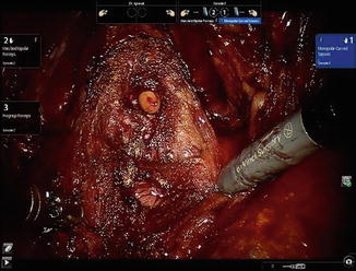
Fig. 13.1
Vacuum bean bag (Hug-U-VacTM, Allen Medical Systems, Acton, MA) to secure patient to the operating table
Compared to the exaggerated Trendelenburg position often used with the transperitonal approach (in order to move the bowels out of the operative field), the extraperitoneal approach allows for a much lesser degree of tilt (about 10–15°).
Access
The main difference between the extraperitoneal and transperitoneal route to performing a robot assisted radical prostatectomy is the access. This consists of creation of the extraperitoneal space and the placement of trocars. Except for minor modifications, all the subsequent steps are similar. With experience, the creation of the extraperitoneal space and trocar placement can be achieved in less than 15 min in the majority of the patients.
Creating the Extraperitoneal Space
Our favored approach is an open Hasson “cut-down” technique. The approach is obtained consistently in a controlled manner with clear visualization of anatomical landmarks. Alternatively, the Visiport optical trocar or the blunt Ethicon Excel optical trocar can be used, as has been described by others [4].
The instruments required to create the potential extraperitoneal space include a OMS-XB2 (Oval) Extraview™ balloon dilator trocar (Autosuture, Norwalk, CT) or a spacemaker ™ trocar, a 0° laparoscope, 2 S-shaped retractors and a 15 cm long smooth trocar (12 mm 512 XD, Ethicon Endo-Surgery, Cincinnati, Ohio) (Fig. 13.2). We prefer to use a separate scope for this step. The robotic camera and scope system are difficult to maneuver due to their weight.
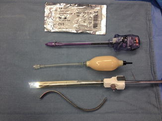

Fig. 13.2
Instruments used during creation of the extraperitoneal space. From top to bottom: Xeroform gauze, long smooth trocar with no ridges (12 mm 512 XD, Ethicon Endo-Surgery, Cincinnati, Ohio), balloon pumping mechanism, OMS-XB2 Extraview™ balloon dilator with the 0° laparoscope placed inside the uninflated balloon, “S” retractor
After a 3 cm left peri-umbilical skin incision, the subcutaneous tissue is bluntly dissected to expose the anterior rectus sheath. A 1 cm incision is made in the latter and an S-shaped retractor is used to sweep the underlying belly of the rectus muscles laterally, to bring the posterior rectus sheath into view. Once the latter is visualized, the balloon dilator is inserted in the space of Retzius, with the scope placed inside the uninflated balloon. The tip of the balloon should be angled upward and toward the midline, to avoid inadvertent injury to the posterior rectus sheath, or access to the peritoneal cavity. There should normally be some resistance from the linea alba until the balloon dilator is passed below the semi-circular line of Douglas. With the start of balloon inflation, the space of Retzius and the retropubic fat are dissected bringing the pubic symphysis into view (Fig. 13.3). The other important landmarks are the inferior epigastric vessels (one artery, two veins) laterally which are visualized on both sides. The external iliac vessels with their attached epigastric tributaries should not be overstretched. Bleeding if present will be noted at this stage with insufflation of the extraperitoneal space. A torn vessel from a branch of the epigastric vessels can be seen at this stage, and can be controlled with a clip. Overdilatation should be avoided as subsequent deflation leads to bleeding. The balloon dilator is removed after deflation and a 15 cm long trocar with the 0° scope is introduced in the space thus created. The key to our approach is the use of this smooth trocar with no ridges. It is useful in the creation of the extra space required for trocar placement cephalad and laterally. This 10/12 mm trocar is wide enough to accommodate the robotic scope. CO2 insufflation of the extraperitoneal space is carried out through the same trocar up to a pressure of 15 mmHg. Under direct vision, the space is further enlarged by retracting the scope into the trocar and using the beveled tip of the trocar (insinuated under the inferior epigastric vessels) to bluntly sweep the peritoneum posterolaterally on either side. It is important to stay between the abdominal wall muscle anteriorly and transversalis fascia posteriorly to avoid creating an inadvertent peritoneotomy which should be suspected if there is billowing. Care should also be taken not to dissect through the overlying muscle fibers. We routinely place a Xeroform gauze around the trocar to prevent CO2 leakage at the camera trocar site. We also use a purse string suture in the fascia to narrow the opening around the trocar and to secure the latter in place. The movements necessary to develop the extraperitoneal space laterally widen the fascial opening, causing leakage of air around the trocar. To lessen air leakage, a balloon tip trocar can be used for this. We prefer the application of the gauze, which quickly seals the opening, obviating the need for trocar exchange.
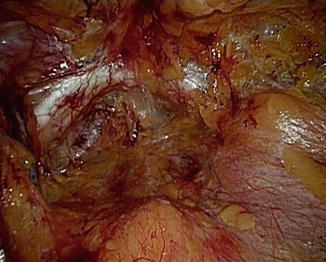

Fig. 13.3
View of the pubic symphysis and extraperitoneal space at the end of balloon dilatation
Trocar Insertion
Robot-assisted procedures call for particular consideration in trocar placement in order to avoid robotic arms collision. A distance of 10 cm between all robotic working arm trocars is important.
Our practice has evolved from a 5-trocar technique to a 6-trocar arrangement in a “W” configuration (Fig. 13.4) during a 4-arm daVinci extraperitoneal robotic prostatectomy. In total, three 8 mm daVinci metal robotic trocars and two disposable assistant trocars (one 12 mm, 150 cm long Excel 512 XD trocar, and one 5 mm trocar) are used in addition to the 12 mm infra-umbilical camera trocar. The 12 mm assistant trocar is used for passage of clips/ sutures while the 5 mm assistant trocar is used for suction/irrigation.
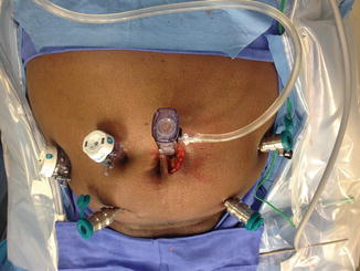

Fig. 13.4
Six trocar “W” configuration. View from the head end. Fourth robotic arm trocar on the left side
Once an adequate space is created, and the peritoneum pushed cephalad and laterally, the 12 mm right assistant trocar is introduced 5 cm medial to the anterior superior iliac spine along a line joining this anatomical landmark to the umbilicus. The assistant trocars can be placed on either side, based on the surgical team’s preference.
The trocar for the fourth robotic arm is placed opposite to the assistant’s (5 cm cephalad and medial to the anterior superior iliac spine) and guided toward the pubic symphysis under direct vision. We use a hypodermic needle to guide the site of insertion of the two remaining robotic working trocars on either side. They are generally placed 10 cm caudal and lateral to the umbilicus on either side, forming a triangle with the latter. Using the needle as a guide to identify the path of the trocars minimizes the risk of inadvertent injury to the epigastric vessels. The trocars for the robotic working arms are placed lateral to the respective epigastric vessels, at a more perpendicular angle to the abdominal wall to avoid robotic arms collision. Trocar tunneling should be avoided, as it will restrict motion of the trocars. For the remaining 5 mm assistant trocar which is placed 5 cm lateral to the umbilicus on the right side, the dissection is performed in a more medial and cephalad direction. The robot is docked once all the trocars are in place (Fig. 13.5).
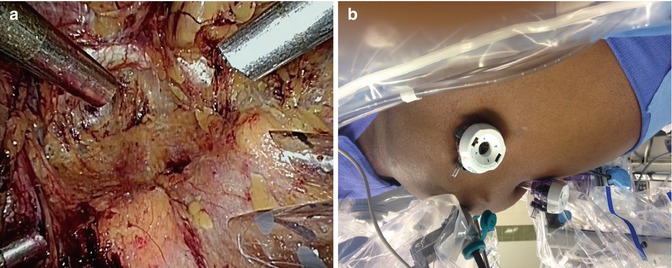

Fig. 13.5
(a) View through the laparoscope of the trocars at the end of their placement. A working robotic trocar with the fourth arm robot trocar on the left side of the patient, and the right working robotic trocar with the two assistant trocars (12 and 5 mm) on the right side of the patient. (b) View from the right side following docking of the robot. Minimal Trendenlenburg position is employed. Selective insufflation of the lower abdomen can be appreciated
We start the procedure with a Maryland bipolar grasper in the left hand, monopolar scissors in the right hand, and Prograsp forceps in the fourth arm. The only other robotic instruments needed are two needle holders used during dorsal vein ligation and completion of vesicourethral anastomosis to be described later. Instruments used by the assistant include suction/irrigation, blunt tip graspers, clip applier and specimen entrapment bag. A 0° scope is used throughout the procedure.
Division of Endopelvic Fascia and Ligation of the Dorsal Venous Complex
The first step following docking of the robot is to incise the endopelvic fascia. One of the advantages of the extraperitoneal approach is evident in this step. The bladder take-down step is eliminated. The endopelvic fascia is often visualized through the balloon dilator as the space is created. If the fascia is not visualized, the loose fatty tissue in the space of Retzius is easily swept off the fascia with all vessels cauterized to ensure hemostasis. Beginning the dissection on the right side and using the left arm to retract the prostate medially, the best plane to enter the endopelvic fascia is identified which is usually a window along the mid portion of the prostate. Allowing air to get behind the fascia helps further delineate the anatomy (Fig. 13.6). This is a generally an avascular plane and can be opened using scissors without cautery. The incision extends from the base of the prostate up to the puboprostatic ligaments. The proper plane of the dissection is where the prostate surface and the pelvic floor muscles are visualized. Once in this plane, the prostatic attachments can be separated by a gentle sweeping motion, pushing the muscles laterally. Dissection toward the puboprostatic ligaments should be performed away from the dorsal venous complex to prevent its inadvertent injury. A combination of delicate sharp as well as blunt dissection is used to free the muscular attachments at the apex of the prostate. We prefer to transect the puboprostatic ligaments as this thins out the dorsal venous complex allowing better coaptation or cinching down of the suture used for its control. Further dissection of the apex of the prostate allows the exposure of the notch between the dorsal venous complex and the urethra where the suture used for venous ligation is placed. We use a barbed V-lock suture on a SH needle to place a figure of eight suture to control the DVC. The needle is held at the junction of its proximal one third at a 30° angle. Guiding it in the correct direction from right to left, parallel to the dorsal venous complex is very important. The tip of the needle is directed toward the previously exposed notch and twisting the needle using the endowrist rather than sliding the needle across the DVC is preferred. The needle should be retrieved following its curve to avoid tearing of dorsal venous complex veins. The suture can be tied, or anchored to the symphysis following dorsal vein ligation. If the needle is placed too posterior, this may lead to capture of the Foley catheter. One should suspect this if the knot does not hold when the vein is being tied. The needle holders should be directed in an anterior-posterior direction during knot tying. Caudal or lateral movement of the needle holders may lead to bleeding due to rubbing of the pubic bones.
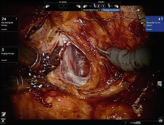

Fig. 13.6
Incision of the endopelvic fascia
Bladder Neck Dissection
In order to expose the plane between the bladder and the prostate, the fourth arm is used to retract the bladder in a postero-cephalad direction. For the novice, where to commence the bladder neck dissection can be challenging. Identifying the waist where the perivesical fat attenuates over the prostate and grasping the tissue with bipolar forceps, taking care not to include the prostate, is a useful starting point. We prefer starting this dissection lateral to the bladder neck where the longitudinal bladder fibers can be easily seen. We use a “burn and push” technique rather than overuse of the cautery to develop the plane between the bladder and the prostate as the latter can lead to creation of multiple planes. The funnel of the bladder neck should be followed to maintain a proper plane. It is very useful to establish this plane laterally and then follow it towards the midline from either side. Following dissection of the anterior bladder neck and confirmation of the correct plane of dissection, a greater appreciation of the planar anatomy between the bladder neck and the prostate can be made on either side. We prefer to transect the bladder neck sharply in the midline. We believe that avoidance of cautery during this step minimizes the risk of bladder neck contracture. The posterior bladder neck fibers are swept off the prostate using a combination of sharp and blunt dissection. Care is taken to carry the dissection in a postero-cephalad direction to follow the normal contour of the prostate which extends cephalad (Fig. 13.7). Identification of the plane between the posterior bladder neck and prostate laterally, and following it medially, minimizes the risk of “button hole” in the posterior bladder neck which may risk injury to the ureteral orifices. Proper traction is important during the bladder neck dissection and the fourth arm is adjusted progressively to help with this.
