Atlas of Abdominal and Pelvic Magnetic Resonance Imaging Anatomy
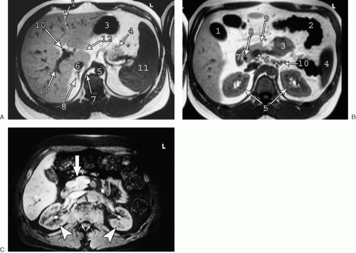 FIG. 4.1. Axial T1-weighted anatomy of abdomen. A: 1, fissure for ligamentum teres; 2, lateral segment left lobe liver; 3, stomach; 4, tail of pancreas; 5, aorta; 6, inferior vena cava; 7, right crus of diaphragm; 8, right adrenal gland; 9, right posterior segment branch portal vein; 10, common hepatic duct; 11, spleen; 12, fissure for ligamentum venosum. B: 1, gallbladder; 2, splenic flexure of colon; 3, small bowel; 4, spleen; 5, kidneys; 6, portal confluence; 7, duodenum, 8, common bile duct; 9, pancreas; 10, left adrenal gland. C: Unenhanced, fat-suppressed T1-weighted image of the abdomen shows relatively high signal intensity of normal pancreas (arrow) and normal corticomedullary differentiation of kidneys (arrowheads). |
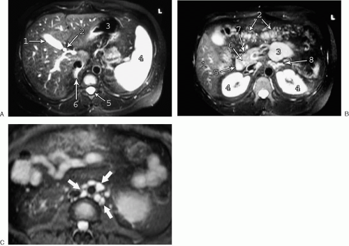 FIG. 4.2. Axial fat-suppressed T2-weighted anatomy of abdomen. A: 1, gallbladder; 2, common hepatic duct; 3, stomach; 4, spleen; 5, spinal canal; 6, right adrenal gland. B: 1, caudal right lobe liver; 2, transverse colon; 3, small bowel; 4, kidneys; 5, duodenum; 6, common bile duct; 7, pancreas; 8, left adrenal gland. C: Lymph nodes are typically very bright on fat-suppressed T2-weighted images as shown in this case of paraaortic lymphadenopathy (arrows). |
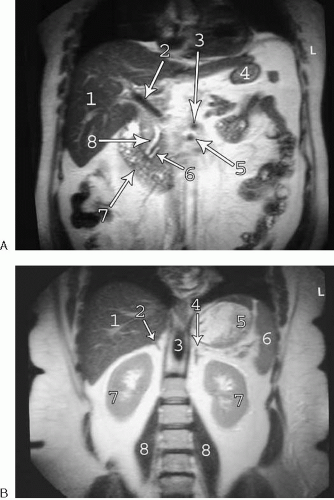 FIG. 4.3. Coronal anatomy of abdomen. A: Coronal HASTE image of anterior abdomen. 1, right hepatic lobe; 2, main portal vein; 3, celiac artery; 4, stomach; 5, superior mesenteric artery; 6, pancreatic duct; 7, duodenum; 8, common bile duct. B: Coronal HASTE image of posterior abdomen. 1, Right hepatic lobe; 2, right adrenal gland; 3, aorta; 4, left adrenal gland; 5, stomach; 6, spleen; 7, kidneys; 8, psoas muscles. |
On T1-weighted images, the normal liver has intermediate signal intensity, but is brighter than the spleen. On T2-weighted images, the spleen normally appears considerably higher in signal intensity than the liver, particularly with fat suppression applied. The division between the right and left hepatic lobes is marked externally by the interlobar fissure. The position of this fissure is best identified on cross-sectional images by a line extending from the gallbladder fossa to the middle hepatic vein. The right hepatic lobe is separated into anterior and posterior segments by the right hepatic vein. The left hepatic lobe is divided into medial and lateral segments by the fissure for the ligamentum teres. The caudate lobe is positioned between the inferior vena cava and the portal vein. A third fissure, the fissure for the ligamentum venosum, extends into the liver anterior to the caudate lobe. The venous drainage of the caudate lobe into the inferior vena cava is independent of the main hepatic veins.
The liver may be further divided into eight numbered (often by Roman numerals) segments based on blood supply and biliary drainage (see Fig. 3.198). The caudate lobe represents segment 1. The left lateral segment consists of segments 2 and 3. The division between segments 2 and 3 is somewhat controversial (left hepatic vein versus left portal vein) but not of great clinical importance, in that resections involving the left lateral segment routinely include both segments 2 and 3. The left portal vein divides the medial left lobe into segments 4a (superior) and 4b (inferior). The right hepatic lobe is divided by the right hepatic and portal veins into four segments arranged clockwise as viewed from the right lateral approach (Fig. 4.4). Segment 5 is anterior to the right hepatic vein and inferior to the right portal vein. Segment 6 is posterior to the right hepatic vein and inferior to the right portal vein. Segment 7 is posterior to the right hepatic vein and superior to the right portal vein, and segment 8 is anterior to the right hepatic vein and superior to the right portal vein.
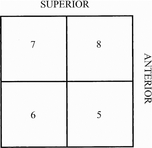 FIG. 4.4. Segmental anatomy of the right hepatic lobe as viewed from the right side. The horizontal line represents the right portal vein. The vertical line represents the right hepatic vein. |
The pancreas, adrenal glands, and kidneys are retroperitoneal structures. The pancreas normally appears relatively bright on T1-weighted images, particularly when fat suppression is applied (see Fig. 4.1C). The pancreatic head is bordered by the duodenum and is traversed by the distal common bile duct. The uncinate process comes to a point dorsal to the superior mesenteric vein. The splenic vein runs along the dorsal surface of the pancreatic body and tail, which are typically 1 to 2 cm thick. The adrenal glands are linear or triangular shaped structures positioned superomedially to the kidneys. The limbs of the adrenal glands typically measure less than 1 cm thick. The kidneys are relatively bright structures on fat-suppressed T2-weighted images and typically demonstrate clearly defined corticomedullary differentiation on fat-suppressed T1-weighted images.
Lymph nodes appear on magnetic resonance (MR) images as round or oval structures distributed adjacent to the blood vessels (after which they are typically named). Lymph nodes demonstrate decreased signal intensity relative to surrounding fat on T1-weighted images and high signal intensity on fat-suppressed T2-weighted images, and they appear as enhancing bright structures on fat-suppressed T1-weighted images after administration of intravenous gadolinium.
Biliary and Pancreatic Ductal Anatomy (Fig. 4.5)
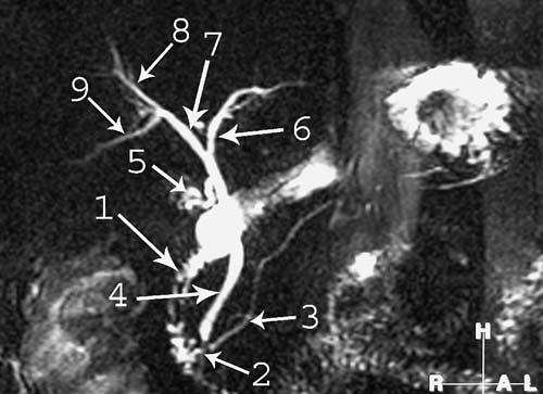 FIG. 4.5. Magnetic resonance cholangiopancreatography anatomy. 1, duodenum; 2, ampulla; 3, pancreatic duct; 4, common bile duct; 5, cystic duct; 6, left hepatic duct, 7, right hepatic duct; 8, right anterior segment duct; 9, right posterior segment duct. Gallbladder has been removed. |
The intrahepatic bile ducts normally join to form three major ducts that are visualized in the majority of patients by magnetic resonance cholangiopancreatography (MRCP)—the right posterior segment duct, the right anterior segment duct (which follows a more craniocaudal course than the posterior segment duct), and the left hepatic duct. The right posterior segment duct (draining segments 6 and 7) and the right anterior duct (draining segments 5 and 8) join to form the right hepatic duct. The right and the left hepatic ducts join to form the common hepatic duct. The cystic duct joins the common
hepatic duct to form the common bile duct. The common bile duct enters the pancreatic head and joins the pancreatic duct near the ampulla. The caudate lobe has its own variable biliary drainage via the right or left hepatic ducts.
hepatic duct to form the common bile duct. The common bile duct enters the pancreatic head and joins the pancreatic duct near the ampulla. The caudate lobe has its own variable biliary drainage via the right or left hepatic ducts.
A wide variety of biliary variants may occur. The most common variant is drainage of the right posterior duct into the distal left hepatic duct (see Fig. 3.200). Also relatively common is a triple confluence, which occurs when the right anterior, right posterior, and left hepatic ducts converge at a single confluence to form the common hepatic duct. In this situation, the right hepatic duct is absent. A large number of other variants may occur, including but not limited to variable insertion of the cystic duct, the right posterior duct draining into the common hepatic duct, cystic duct, or right side of the right anterior duct, and accessory right and left hepatic ducts with variable drainage.
Related posts:
 Basic Magnetic Resonance Imaging Principles for the Abdomen and Pelvis
 Magnetic Resonance Cholangiopancreatography
 Magnetic Resonance Urography
 Modifying Sequence Parameters
 Glossary of Magnetic Resonance Imaging Terms
 What the Surgeon Needs to Know: Preoperative Assessment of Patients with Selected Tumors and Organ Transplant Candidates
Stay updated, free articles. Join our Telegram channel

Full access? Get Clinical Tree


