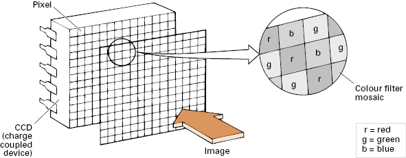
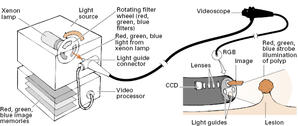
The image is captured with a charge-coupled device (CCD) chip, transmitted electronically, and displayed on a video monitor. Individual pixels (photo cells) in the CCD chips can respond only to degrees of light and dark. Color appreciation is arranged by two methods. So-called “color CCDs” have their pixels arranged under a series of color filter stripes (Fig 2.2). By contrast, “monochrome CCDs” (or, more correctly, sequential system CCDs) use a rotating color filter wheel to illuminate all of the pixels with primary color strobe-effect lighting (Fig 2.3). This type of chip can be made smaller, or can give higher resolution, but the system is more expensive because of the additional mechanics and image-processing technology.
“Electronic chromoendoscopy” systems are now standard in many endoscopes, allowing enhancement of aspects of the surface of the gastrointestinal mucosa. Narrow band imaging (NBI; Olympus Corporation) uses optical filters to select certain wavelengths of light, which correspond to the peak light absorption of hemoglobin, enhancing the visualization of blood vessels and certain surface structures. The Fuji Intelligent Chromo Endoscopy (FICE; Fujinon Endoscopy) and i-Scan (Pentax Medical) systems take ordinary endoscopic images and digitally process the output to estimate different wavelengths of light, providing a number of different imaging outputs. Autofluorescence imaging can detect endogenous fluorophores, a number of which occur in the gastrointestinal tract. Two systems now also allow magnification of the endoscopic image down to the cellular level: termed confocal microscopy (Pentax Medical, Mauna Kea Technologies). Blue laser light is focused on the desired tissue after injecting fluorescent materials, which become excited by the laser light and are detected at defined horizontal levels.
Tip control
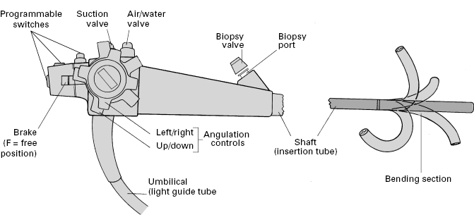
The distal bending section (10 cm or so) and tip of the endoscope is fully deflectable, usually in both planes, up to 180° or more. Control depends upon pull wires attached at the tip just beneath the outer protective sheath, and passing back through the length of the instrument shaft to the two angulation control wheels (for up/down and right/left movement) on the control head (Fig 2.4). The wheels incorporate a friction braking system, so that the tip can be fixed temporarily in any desired position. The instrument shaft is torque stable, so that rotating movements applied to the head are transmitted to the tip when the shaft is relatively straight.
Instrument channels and valves
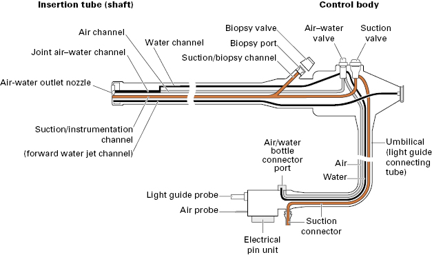
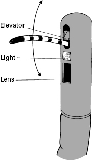
The internal anatomy of endoscopes is complex (Fig 2.5). The shaft incorporates a biopsy/suction channel extending from the entry “biopsy port” to the tip of the instrument. The channel is usually about 3 mm in diameter, but varies from 1 to 5 mm depending upon the purpose for which the endoscope was designed (from neonatal examinations to major therapeutic procedures). In some instruments, especially those with lateral-viewing optics, the tip of the channel incorporates a deflectable elevator or bridge (see Fig 2.7), which permits directional control of forceps and other accessories independent of the instrument tip. This elevator is controlled by an additional thumb lever. The biopsy/suction channel is used also for aspirating secretions: an external suction pump is connected to the universal cord near to the light source, and suction is diverted into the instrument channel by pressing the suction valve. Another small channel allows the passage of air to distend the organ being examined. The air is supplied from a pump in the light source and is controlled by another valve. For colonoscopy, the air insufflation system can be modified to CO2 rather than room air and has been shown to lessen abdominal distension and pain after colonoscopy. The air system also pressurizes the water bottle, so that a jet of water can be squirted across the distal lens to clean it.
Different instruments
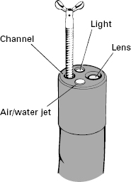
The endoscopy unit must have a selection of endoscopes for specific applications. These may differ in length, size, stiffness, channel size and number, sophistication, and distal lens orientation. Most endoscopies are performed with instruments providing direct forward vision, via a wide-angle lens (up to 130°) (Fig 2.6). However, there are circumstances in which it is preferable to view laterally, particularly for endoscopic retrograde cholangiopancreatography (ERCP) (Fig 2.7).
The overall diameter of an endoscope is a compromise between engineering ideals and patient tolerance. The shaft must contain and protect many bundles, wires, and tubes, all of which are stronger and more efficient when larger (Fig 2.5). A colonoscope can reasonably approach 15 m in diameter, but this size is acceptable in the upper gut only for specialized therapeutic instruments.
Routine upper endoscopy is mostly performed with instruments of 8–11 mm diameter. Smaller endoscopes are available; they are better tolerated by all patients and have specific application in children. Some can be passed through the nose rather than the mouth. However, smaller instruments inevitably involve some compromise in durability, image quality, maneuverability, biopsy size, and therapeutic potential.
Several companies now produce a full range of endoscopes at comparable prices. However, light sources and processors produced by different companies are not interchangeable, so that most endoscopy units concentrate for convenience on equipment from a single manufacturer. Endoscopes are delicate, and some breakages are inevitable. Careful maintenance and close communication, repair, and back-up arrangements with an efficient company are necessary to maintain an endoscopy service. The quality of that support is often a crucial factor affecting the choice of company.
Endoscopic accessories
Many devices can be passed through the endoscope biopsy/suction channel for diagnostic and therapeutic purposes.
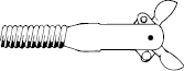
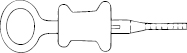
- Biopsy forceps consist of a pair of sharpened cups (Fig 2.8), a spiral metal cable, a pull wire, and a control handle (Fig 2.9). Their maximum diameter is limited by the size of the channel, and the length of the cups by the radius of curvature through which they must pass in the instrument tip. When taking biopsy specimens from a lesion that can only be approached tangentially (e.g. the wall of the esophagus), forceps with a central spike may be helpful; however, these do present a significant puncture hazard for staff.
- Cytology brushes have a covering plastic sleeve to protect the specimen during withdrawal (Fig 2.10).
- Flexible needles are used for injections and for sampling fluids and cells.
- Fluid-flushing devices. Most instruments have a flushing jet channel to keep the lens clean. Fluids can also be forcibly flushed through the instrumentation channel with a large syringe or a pulsatile electric pump, with a suitable nozzle inserted into the biopsy port. For more precise aiming, a washing catheter can be passed down the channel to clean specific areas of interest, or to highlight mucosal detail by “dye spraying” (using a nozzle-tipped catheter).

Ancillary equipment
- Suction traps (fitted temporarily into the suction line) can be used to take samples of intestinal secretions and bile for microbiology, chemistry, and cytology (Fig 2.11; see also Fig 7.27).
- Biteguards are used to protect the patient’s teeth and the endoscope. Some guards have straps, to keep them in place, and oxygen ports.
- Overtubes are flexible plastic sleeves that cover the endoscope shaft and act as a conduit for repeated intubations, or to facilitate therapeutic procedures such as the extraction of a foreign body and hemostasis (Fig 2.12).
- Caps of various shapes can be attached to the tip of the endoscope to facilitate various procedures, such as banding and mucosal resection, dissection, etc.
- Stretchers/trolleys. Endoscopy is normally performed on a standard transportation stretcher. This should have side rails, and preferably allow height adjustment. The ability to tilt the stretcher head down may be helpful in emergencies.
- Image documentation
Related posts:

Stay updated, free articles. Join our Telegram channel

Full access? Get Clinical Tree


