The success of peritoneal dialysis as renal replacement therapy hinges upon the patient possessing a functional peritoneal access. In the present era, access is obtained using a catheter device that bridges the abdominal wall and serves as a controlled cutaneoperitoneal fistula. Similar in principle to creation of an arteriovenous access for hemodialysis, provision of a peritoneal access must consider a number of patient factors that can influence flow function, durability, and resistance to complications.
I. ACUTE AND CHRONIC CATHETERS. Based on design and use, catheters can be classified as acute or chronic.
A. Acute catheters
1. Rigid noncuffed catheters. Composed of relatively rigid plastic, these noncuffed tubes are provided in straight and slightly curved configurations with numerous side holes in the intraperitoneal segment. Insertion is performed by percutaneous puncture using an internal stylet. Because of the risk of infection, the generally accepted period of maximum use is 3 days. If a short course of peritoneal dialysis is anticipated or therapy must be initiated before a chronic catheter can be placed, the temporary rigid catheter remains an option. These devices are available in kits containing the catheter, connecting tubing, and a scalpel.
2. Soft cuffed catheters. Most of the chronic catheters described more fully in the following section can serve as acute peritoneal access devices and are generally available in self-contained sets, permitting bedside placement using a percutaneous needle–guidewire approach to insert a peel-away catheter introducer sheath. If it is anticipated that the need for peritoneal dialysis will be longer than a few days, a chronic catheter should be placed initially, whenever possible. While the trend for chronic catheters is to use two-cuff devices, one of the continuing demands for a single-cuff catheter is to provide acute access. Compared to the rigid catheter, the one-cuff soft tube can be left in place indefinitely, and it is easier to insert and remove than two-cuff chronic devices. If long-term dialysis is likely and the patient’s clinical condition permits, consideration should be given to implanting a chronic catheter with at least two cuffs.
B. Chronic catheters. Presently, all chronic catheters are constructed of silicone rubber, a material well recognized for its biocompatibility and biodurability. A small percentage of catheters were previously constructed from polyurethane rubber, but these have not been commercially available since 2010. Although the number of surviving polyurethane devices is rapidly diminishing, it is important to identify these catheters because of the tendency of polyurethane rubber to develop stress fractures or to soften and rupture from chronic exposure to polyethylene glycol or ethanol present in certain topical antibiotic ointments and creams commonly used for chronic catheter exit-site prophylaxis. Polyurethane catheters can be recognized by a permanently bonded catheter adapter and they typically show permanent dark discoloration of the tubing after several years.
Figure 23.1 depicts a chronic peritoneal catheter showing its relationship to abdominal wall structures. Chronic catheters are most commonly supplied with two Dacron (polyester) cuffs, but as many as three cuffs may be present in extended two-piece catheters. Having at least two cuffs provides for better immobilization of the catheter in the abdominal wall. The deep cuff is preferably implanted in the muscle to provide for firm tissue ingrowth and fixation of the catheter. The superficial cuff is positioned in the subcutaneous tissues 2–4 cm from the exit site. When properly positioned, the superficial cuff serves as an effective barrier to entry of cutaneous debris and bacteria into the subcutaneous track and acts to limit the piston-like motion of the catheter in and out through the exit site that can drive these contaminants into the track.
The intraperitoneal segment of the catheter tubing has either a coiled-tip or straight-tip configuration with an end hole and numerous side holes. No significant difference in functionality has been demonstrated between coiled- and straight-tip catheters; however, previous randomized comparative studies involved small subject numbers with equivocal results, and the validity of a recent meta-analysis favoring straight-tip catheters is debatable. The incidence of inflow discomfort is greater with straight-tip catheters due to the jet effect of the dialysate from the end hole of the catheter. Coiled-tip catheters provide for better dispersion of the dialysate during inflow.
All recently manufactured chronic catheters incorporate a white radiopaque stripe along the longitudinal axis of the tubing which enables radiographic visualization. The stripe can also serve as a guide during implantation of the catheter to prevent accidental twisting or kinking of the catheter tubing. The majority of adult catheters have a 2.6-mm internal bore. One catheter brand possesses a 3.5-mm bore and can be identified by its blue radiopaque stripe. While in vitro flow rates of the larger bore catheter are faster, this has not been so apparent in the in vivo state. The importance of recognizing the catheter bore size is to prevent inadvertent interchange of replacement catheter adapters that can result in a loose fit and accidental separation.
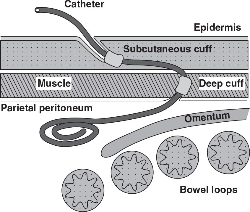
FIGURE 23.1 Schematic of a coiled-tip Tenckhoff peritoneal catheter showing its proper relationship to adjacent anatomical structures.
1. Standard abdominal catheters. The coiled- and straight-tip Tenckhoff catheters and their “swan neck” variants with a preformed arc bend in the intercuff segment are illustrated in Figure 23.2A,B. These four catheters comprise the mainstay of peritoneal access around the world. The primary difference among these catheters is that the coiled-tip configuration and preformed arc increase the cost of the device. Standard abdominal catheters can be inserted by any of the implantation methodologies.
2. Extended two-piece catheters. Originally designed as a presternal catheter, the extended catheter comprises a one-cuff abdominal catheter segment that attaches to a subcutaneous extension segment having one or two cuffs by using a titanium connector to permit remote location of the exit site to the upper chest (Fig. 23.2C). It has since been used to provide remote locations of exit sites to the upper abdomen or the back region. The abdominal catheter can be placed by any insertion method. The subcutaneous extension catheter is implanted using a vascular tunneling rod or a similar device supplied by the catheter manufacturer.
3. Alternative catheter designs. Modifications of the basic Tenckhoff catheter design have been made to address problems with tissue attachment, tip migration, and pericatheter leaks. The Oreopoulos–Zellerman (Toronto Western) variation of the straight-tip catheter includes the addition of two silicone disks to the end of the tubing in an attempt to hold bowel and omentum away from the side holes (Fig. 23.2D). The Di Paolo catheter is designed to discourage catheter tip migration by adding a tungsten weight to the end of the tubing to promote gravitational self-location to the pelvis (Fig. 23.2E). The Oreopoulos–Zellerman and Missouri catheters have a Dacron flange adjacent to a silicone bead mounted below and contiguous with the deep cuff (Fig. 23.2F). The flange and bead are attached at a 45-degree angle on the Missouri version. Suturing the peritoneum between the flange and bead and stitching the flange to the posterior rectus sheath were designed to reduce the occurrence of pericatheter leaks. Mounting the flange and bead at a 45-degree angle was intended to keep the catheter tip oriented toward the pelvis. None of the alternative configurations have been shown to outperform the standard Tenckhoff catheter design, but do increase the cost and difficulty of device insertion.
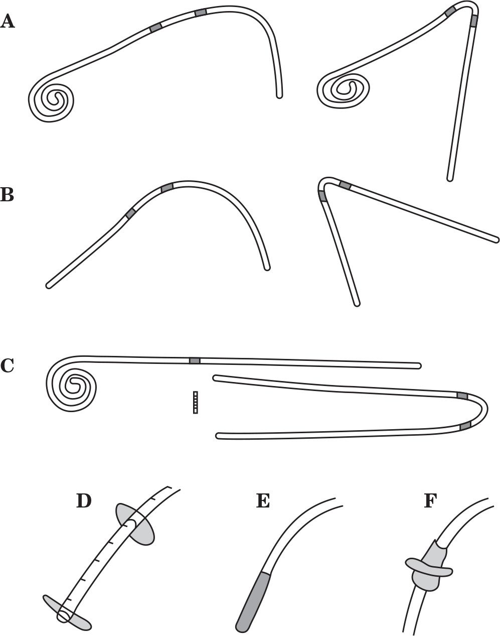
FIGURE 23.2 Shown are commonly used peritoneal catheters and alternative design features. A: Tenckhoff catheters with coiled-tip, two-cuff, and straight or swan neck intercuff segment. B: Tenckhoff catheters with straight-tip, two-cuff, and straight or swan neck intercuff segment. C: Extended catheter with coiled-tip, one-cuff abdominal catheter, two-cuff extension catheter with swan neck intercuff segment, and titanium connector. D: Straight-tip catheter with silicone disks. E: Straight-tip catheter with tungsten weight. F: Dacron flange and silicone bead below and adjoining the deep cuff.
II. CATHETER SELECTION
A. Patient factors influencing catheter selection. Patients come in all sizes and shapes with a variety of medical conditions; therefore, it is somewhat naive to expect that one catheter type should fit all. Choice of catheter type should take into consideration the patient’s belt line, obesity, skin creases and folds, presence of scars, chronic skin conditions, incontinence, physical limitations, bathing habits, and occupation. A basic inventory of several catheter types is required to provide customization of the peritoneal access to the specific needs of the patient and to afford maximum flexibility in exit-site location. Figure 23.3 illustrates how a basic catheter inventory might be applied. Patients who wear their belt lines above the umbilicus are often best served with a catheter with a swan neck bend that allows the exit site to emerge below the belt line. Patients who wear their belt lines below the umbilicus are usually best fitted with a catheter having a straight intercuff segment that is bent to produce a laterally directed exit site emerging above the belt line. Individuals who have large rotund abdomens, severe obesity, drooping skin folds, intestinal stomas, feeding tubes, urinary or fecal incontinence, yeast intertrigo, or desire to take deep tub baths are ideal candidates for extended catheters to produce upper abdominal or presternal exit sites.
B. Stencil-based preoperative mapping. Some dialysis catheter manufacturers produce marking stencils for the most commonly used catheter designs. Properly constructed stencils contain critical catheter design information, including the distance between the deep cuff and the coil, suggested subcutaneous tunnel configurations, and recommended exit-site locations relative to the position of the superficial cuff. Additional features of a well-designed stencil plate permit its precise orientation on the trunk region according to fixed anatomical landmarks, such as the pubic symphysis (representing the anterior upper border of the true pelvis) and the anatomical midline of the torso. Stencils permit accurate and reproducible association of the catheter design elements to these anatomical landmarks to help determine the best catheter style and insertion site that will produce optimal pelvic position of the catheter coil and ideal exit-site location.
Figure 23.4 shows the use of the stencil for lower abdominal, upper abdominal, and chest catheter exit-site locations. The stencil should be initially used during a preoperative evaluation where the patient can be examined fully clothed and in supine, sitting, and/or standing positions. The stencil can also be used at the time of the catheter insertion procedure to mark and/or verify the markings made during the preoperative examination. During the preoperative mapping session in which the most appropriate catheter style is selected, only the exit-site cutouts need to be marked. At the time of the procedure, the entire pattern including incision marks, tunnel track, cuff and exit-site cutouts are marked.
During the preoperative examination, the stencil is used to mark the exit sites of the standard abdominal catheters while the patient is supine. The patient then assumes a sitting or standing position, and the marked exit sites are checked to see which is best visible to the patient and does not conflict with the belt line, skin creases, or apices of bulging skin folds. If none of the marked exit sites for the standard abdominal catheters are satisfactory, the stencil is then used to map out either upper abdominal or presternal exit-site locations. Be aware that some manufacturers produce impractical stencils that show only the cutout pattern of a swan neck bend but do not allow for proper alignment of the stencil plate on the abdominal or chest wall.
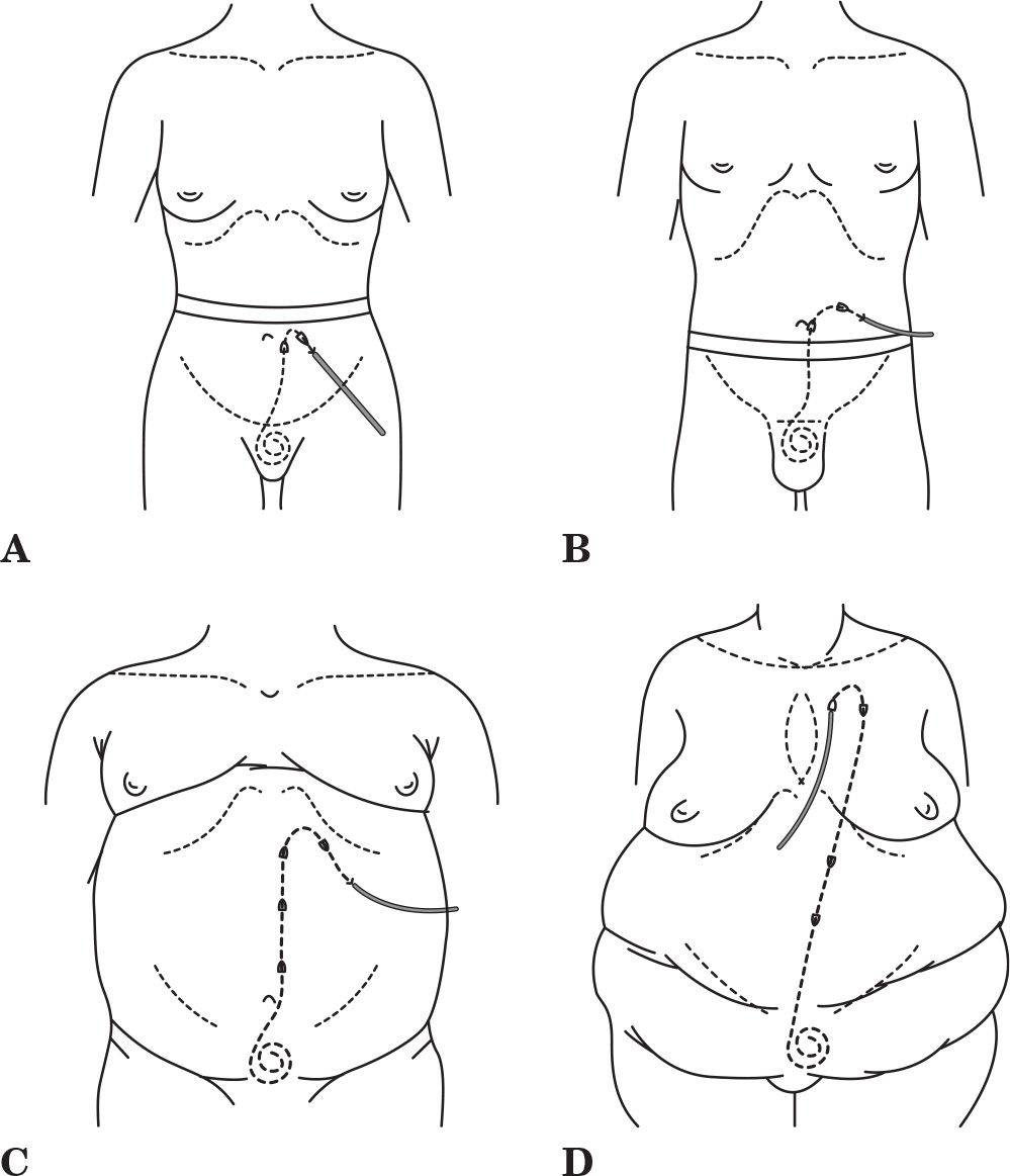
FIGURE 23.3 Practical applications of a basic catheter inventory. A: Swan neck catheter with downwardly directed exit site emerging below a high-lying belt line. B: Straight intercuff segment catheter with laterally directed exit site emerging above a low-lying belt line. C: Extended catheter with upper abdominal exit site for an obese rotund abdomen, lower abdominal skin folds, or incontinence. D: Extended catheter with upper chest exit site for severe obesity, multiple abdominal skin folds, intestinal stomas, or incontinence.
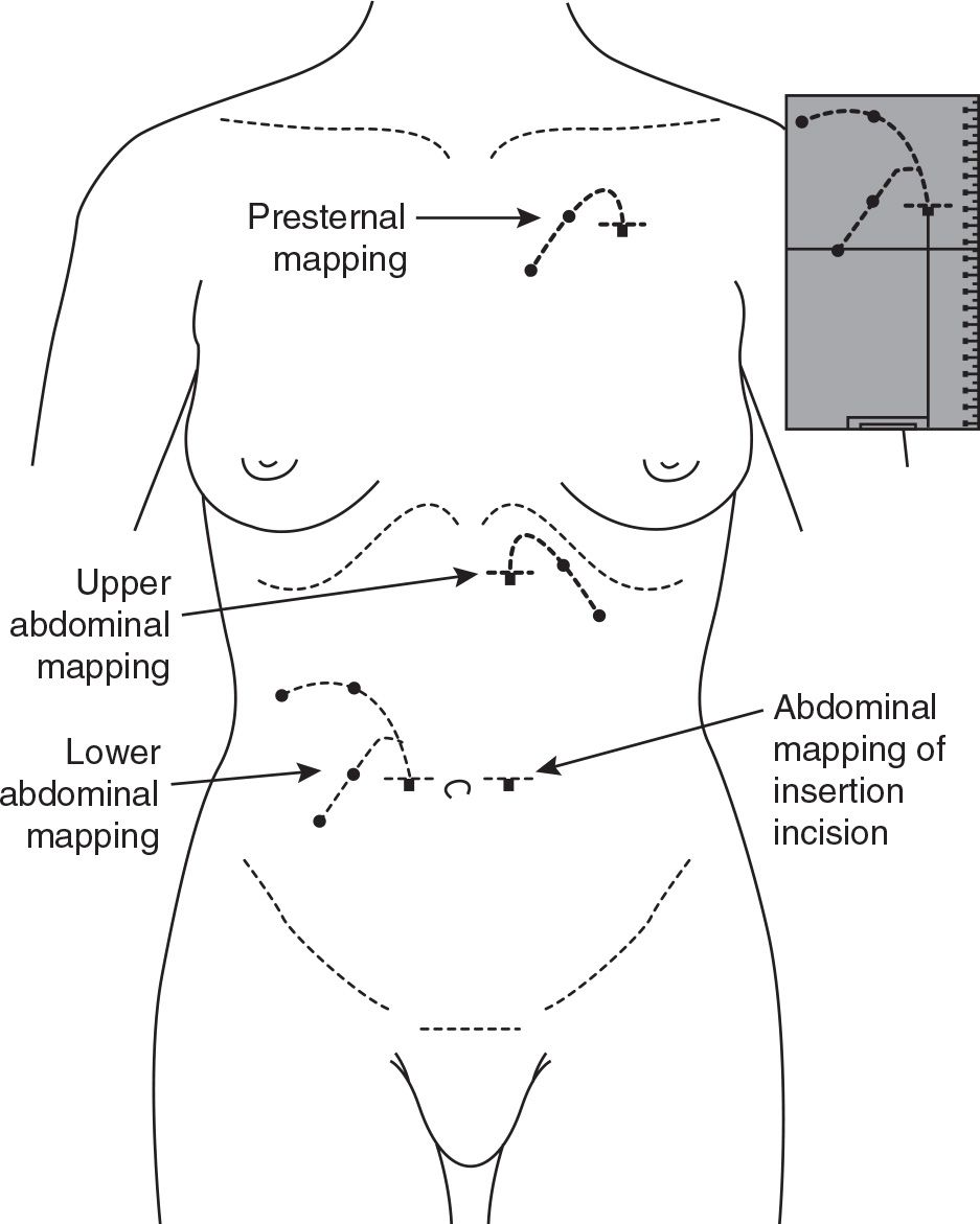
FIGURE 23.4 Stencil-based preoperative mapping for standard abdominal and extended catheters. This allows for selection of the most appropriate device type and insertion site that will produce the best pelvic position of the catheter tip and the optimal exit-site location, based on patient-specific anatomical features.
III. CATHETER PLACEMENT PROCEDURES
A. Best practices. A best practice is a technique or methodology that, through experience and research, has proven to reliably lead to a desired result. Best practices for preoperative preparation and peritoneal catheter placement are listed in Tables 23.1 and 23.2. Adherence to a constellation of details is required to assure the best opportunity for creating a successful long-term peritoneal access. Omission of any one of these best practices can lead to loss of the peritoneal catheter. It is recognized that some implantation techniques do not incorporate all of the best practices, such as percutaneous needle–guidewire approaches performed through the midline or positioning the deep cuff above the level of the fascia. It is enough that the practitioner be aware of the deviations from recommended practice and be observant of the potential complications that may arise from such departures. In addition, some of the listed best practices will not be applicable to acute noncuffed temporary catheters.
Best Practices in Patient Preparation for PD Catheter Insertion | |
• Preoperative assessment to select the most appropriate catheter type and exit-site location
• Bowel prep the day before surgery: 2 L of polyethylene glycol solution, enema, or stimulant suppository
• Shower on the day of surgery with chlorhexidine soap wash of the abdomen/chest
• Removal of body hair in the preoperative holding area, preferably with electric clippers
• Empty the bladder before procedure; otherwise, Foley catheter should be inserted
• Single preoperative dose of prophylactic antibiotic to provide antistaphylococcal coverage
Best Practices for PD Catheter Insertion | |
• Operative personnel are attired in cap, mask, and sterile gown and gloves
• Surgical site is prepped with chlorhexidine–gluconate scrub, povidone–iodine (gel or scrub), or other suitable antiseptic agent and sterile drapes applied around the surgical field
• Peritoneal catheter is rinsed and flushed with saline and air squeezed out of the Dacron cuffs by rolling the submerged cuffs between fingers
• Paramedian insertion of the catheter through the body of the rectus muscle
• Deep catheter cuff positioned within or below the rectus muscle
• Pelvic location of the catheter tip
• Catheter flow test performed to confirm acceptable function
• Skin exit site directed lateral or downward (not upward)
• Subcutaneous tunneling instrument should not exceed the diameter of the catheter
• Exit site should be smallest skin hole possible that allows passage of the catheter
• Position subcutaneous cuff 2–4 cm from the exit site
• No catheter anchoring sutures at the exit site
• Attach transfer (extension) set at time of procedure
• Exit site protected and catheter immobilized by nonocclusive dressing
B. Acute noncuffed catheter insertion. The semirigid acute catheter is inserted by percutaneous puncture using an internal stylet. A 1-cm midline or paramedian skin incision is made approximately 2.5 cm below the level of the umbilicus. A hemostat clamp is used to spread down to the fascia. The stylet is inserted into the catheter until the pointed tip is exposed. Depth of penetration is controlled by grasping the catheter–stylet assembly with the thumb and index finger. With the patient tensing the abdominal musculature, the catheter–stylet assembly is advanced through the musculofascial layer with a twisting motion under constant controlled pressure until a “pop” or sudden drop in resistance is sensed, indicating entry into the peritoneal cavity. The patient is allowed to relax the abdominal muscles. Holding the catheter in place, the stylet is immediately withdrawn several centimeters to “hide” the pointed end. Gently, the catheter is advanced toward the pelvis without moving the stylet until satisfactory depth has been achieved. The stylet is removed, and the administration set is attached to the catheter. A suture or catheter holder is used to secure the temporary catheter. Alternatively, the abdomen may be prefilled with 1–2 L of dialysis solution before inserting the catheter–stylet. A Veress needle (a Veress needle is a spring-loaded needle used to create pneumoperitoneum for laparoscopic surgery) or a 16G–18G intravenous cannula is inserted into the peritoneal cavity through the incision described earlier to perform the prefill.
C. Chronic catheter placement. Methods for insertion of chronic peritoneal catheters include placement by percutaneous guidewire technique (performed blindly or with image guidance), the YTEC laparoscopic-assisted approach, open surgical dissection, and laparoscopic implantation. Optionally, the implantation technique may include extending the catheter to a remote exit-site location and/or embedding the external limb of the catheter tubing under the skin with delayed externalization when initiation of dialysis is needed. An overview of each of the implantation approaches will be presented.
1. Percutaneous needle–guidewire technique. Placement of catheters by blind percutaneous puncture is performed using a modification of the Seldinger technique. The convenience of this approach is that it can be performed at the bedside under local anesthesia using prepackaged self-contained kits that include the dialysis catheter. The abdomen is prefilled with 1.5–2 L dialysis solution instilled with an 18G introducer needle inserted through a 1.5- to 2-cm infraumbilical or paramedian incision. Alternatively, a Veress needle may be used to perform the prefill. A guidewire is passed through the needle into the peritoneal cavity and directed toward the retrovesical space. The needle is withdrawn. A dilator with overlying peel-away sheath is advanced through the fascia over the guidewire. The guidewire and dilator are removed. Stiffened over a stylet, the dialysis catheter is directed through the sheath toward the pelvis. As the deep catheter cuff advances, the sheath is peeled away. The deep cuff is advanced to the level of the fascia.
The addition of fluoroscopy to the procedure permits confirmation of needle entry into the peritoneal cavity by observing the flow of injected contrast solution around loops of bowel. The retrovesical space is identified by contrast pooling in the appropriate location. The guidewire and catheter are advanced to this site. Ultrasonography can be used in a similar fashion. The remainder of the procedure is as described for blind placement. Although the radiopaque tubing stripe permits fluoroscopic imaging of the final catheter configuration, the proximity of adhesions or omentum cannot be assessed. Percutaneous guidewire placement techniques usually leave the deep catheter cuff external to the fascia. After testing flow function, the catheter is then tunneled subcutaneously to the selected exit site.
Related posts:


Stay updated, free articles. Join our Telegram channel

Full access? Get Clinical Tree


