Fig. 13.1
The operating room monitor is configured to show the sonographic and laparoscopic images simultaneously in a “picture-in-picture” view
LUS Technique
Initial Dissection
Although some authors have described the use of LUS during laparoscopic cholecystectomy immediately upon establishment of pneumoperitoneum, during routine cases we prefer to perform an initial dissection of the hepatocystic triangle prior to sonographic examination. Using a standard four-port technique, a combination of blunt and electrocautery dissection is used to remove all of the fibrous and fatty tissue from the hepatocystic triangle in order to establish a “critical view of safety” [7]. Reserving use of LUS until after this dissection has been performed offers several advantages. The most important is that a meticulous and thorough dissection is the most essential means to preventing CBD injury [4]. By completing this dissection prior to the LUS examination, the surgeon does not run the risk of being misled by a seemingly normal anatomic configuration on ultrasound. Additionally, opening the hepatocystic triangle via dissection allows for an easier and more complete LUS examination. The gallbladder is freed from the inferior aspects of its peritoneal attachments to the liver bed, enabling retraction of the infundibulum further laterally from the cystic duct-CBD junction. This allows for easier LUS identification and delineation of the ductal structures and enables the surgeon to manipulate the infundibulum with more mobility during LUS to create a variety of viewing angles.
If there is uncertainty regarding the anatomy during the course of the dissection to create a “critical view,” LUS can be employed earlier to examine the ducts in relation to the area in question. In the case of a difficult or confusing dissection, LUS and IOC can be employed conjointly to establish a more robust anatomic examination. However, LUS and IOC should be only considered tools that provide additional information, rather than definitive evaluations. If any uncertainty exists regarding the anatomic relationships of the critical ductal and/or vascular structures after the use of these modalities, the surgeon should not hesitate to convert to an open procedure in order to ensure optimal safety.
Intraoperative Scanning
Once a dissection to a “critical view” has been completed, the ultrasound probe is connected to the scanner and the monitors are switched to a “picture-in-picture” view. Using the standard “American” four-port configuration, the ultrasound probe can be introduced through either the epigastric or umbilical trocar. While we prefer the epigastric technique, each method has its own advantages and disadvantages. Often when a certain structure or segment of the CBD cannot be visualized via one trocar, the probe position must be switched, and some authors have advocated routine imaging from both orientations in every case. While we have found this to be infrequently necessary, surgeons must have a good familiarity with both techniques.
Epigastric Scanning Technique
When scanning through the epigastric trocar, the surgeon stands on the patient’s left side and manipulates the probe with his or her right hand while the left hand retracts the gallbladder infundibulum using a grasper placed through the more medial of the two right-subcostal trocars. The assistant retracts the gallbladder fundus superiorly over the liver through the lateral subcostal trocar and operates the camera. The probe is inserted in the direction of the gallbladder, with the scanning array facing posteriorly. It is helpful to hold the probe with your index finger positioned on the side opposite to the scanning array in order to maintain spatial orientation during subsequent probe maneuvering.
The probe is first positioned directly over the gallbladder wall. The sonographic depth of field and gain can then be adjusted to optimize the image. Fluid inside the gallbladder should appear anechoic (i.e., black), and any stones should be hyperechoic (i.e., white) and create “shadowing” in the sonographic field beyond their location (Fig. 13.2). When scanning through the gallbladder, other pathology such as polyps can be identified. In contrast to stones, polyps will appear less hyperechoic, will not create shadowing, and will not fall to a dependent location within the gallbladder. (Refer to Chap. 5 for more detail.)
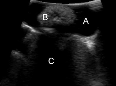
Fig. 13.2
The gallbladder is imaged, showing anechoic gallbladder fluid (A), a large hyperechoic stone (B), and sonographic shadowing (C) created by the stone
Once the sonographic view has been fine-tuned and the gallbladder inspected, the probe is placed over the midportion of the hepatoduodenal ligament with the scanning array facing posteriorly (Fig. 13.3). The probe is then manipulated in order to visualize the portal triad structures: the CBD, proper hepatic artery, and portal vein. The probe is positioned perpendicular to the hepatoduodenal ligament, and as a result, all three structures are seen in a transverse orientation and appear as circles on the sonographic image. The CBD and hepatic artery are usually smaller in diameter and aligned in the same anterior-posterior plane, ventral to the larger portal vein. This normal configuration creates a so-called Mickey Mouse head sonographic appearance (Fig. 13.4).
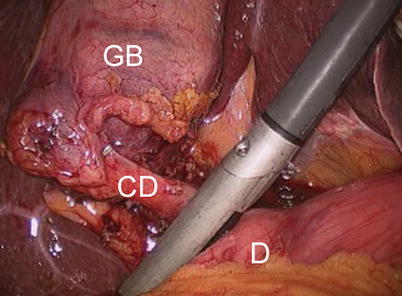
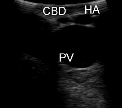
Fig. 13.3
The starting position for imaging the biliary tree when scanning through the epigastric trocar. The probe is placed over the midportion of hepatoduodenal ligament, superior to the duodenum (D) and inferior to the cystic duct (CD) and gallbladder (GB)
Fig. 13.4
The portal triad is visualized, creating a “Mickey Mouse head” appearance of the common bile duct (CBD) and proper hepatic artery (HA) anteriorly and portal vein (PV) posteriorly, all seen in transverse section
The probe is then moved caudad down the hepatoduodenal ligament and toward the duodenum in order to scan the length of the CBD. During this step the surgeon should manipulate the probe slowly, while only moving in a single plane without rotation. This will allow for visualization of the entire length of the suprapancreatic CBD and minimize the risk of skipping over a segment of duct that contains a stone. The probe should rest gently on the hepatoduodenal ligament during this step. If too much pressure is applied, the CBD will be compressed and obscured from view. Conversely, if the probe is lifted off the surface of the ligament, the acoustic window and sonographic image will be lost. This can be an issue in very thin patients in whom the hepatoduodenal ligament is devoid of fat. To remedy this problem, saline can be infused to flood the right upper quadrant and act as an acoustic coupler in order to create a better acoustic window [8]. However, in actual practice we have found this to be rarely necessary, as well as additionally time consuming.
As the CBD is sequentially imaged, the surgeon should be primarily looking for intraductal stones and sludge. Stones appear intensely hyperechoic and create acoustic shadowing on the side opposite to the scanning array (i.e., toward the bottom side of the sonographic image) (Fig. 13.5). Once detected, the diameter of a stone can be measured using the sonographic calipers function. This can be helpful in determining the most effective means of stone removal via laparoscopic or open CBD exploration or endoscopic retrograde cholangiopancreatography (ERCP). Sludge is defined as echogenic intraductal debris consisting of particles less than 1 mm in diameter and does not usually result in shadowing [9]. During our initial experience with LUS, we would attempt to treat all findings of CBD sludge with flushing via a catheter introduced into the cystic duct [10]. However, we have found this sludge to most often be of no clinical consequence and now reserve intervention for cases in which it is causing biliary obstruction or pancreatitis [11].
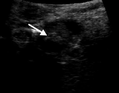
Fig. 13.5
A hyperechoic stone (arrow) visualized within the common bile duct
After imaging of its suprapancreatic portion, the CBD is followed distally as it enters the pancreatic parenchyma. As the CBD enters the pancreas, its path deviates to the patient’s right side, toward the ampulla of Vater. In order to follow the duct along this course, the LUS probe is held in a stationary position abutting the superior edge of the duodenum and slowly rotated in a clockwise direction. With this motion, the CBD should be kept in a transverse orientation on the sonographic image (Fig. 13.6). The duct should be followed until its entrance into the duodenum. The muscular sphincter of the ampulla can be seen as a hypoechoic ring surrounding the distal most segment of the duct (Fig. 13.7). Additionally, the pancreatic duct can often be seen traversing the pancreas inferior to the CBD. In certain patients a long common segment of CBD-pancreatic duct exists and can be documented sonographically, which may predispose to the development of gallstone pancreatitis.
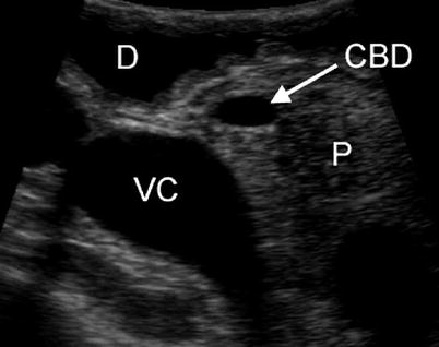
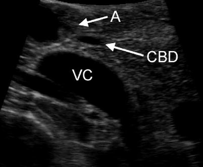
Fig. 13.6
The common bile duct (CBD) is seen transversing the relatively hyperechoic pancreatic parenchyma (P). The duodenum (D) anteriorly and inferior vena cava (VC) posteriorly are also visualized
Fig. 13.7
The distal common bile duct (CBD) is seen just as it enters the duodenum through the ampulla of Vater (A). The inferior vena cava (VC) is seen posterior to the pancreas
Pancreatic tissue is relatively hyperechoic compared with the fatty tissue of the hepatoduodenal ligament. This can make detection of CBD stones more difficult in the ductal segment within the pancreas. In many series, rates of complete visualization and stone detection in the intrapancreatic (distal) CBD are lower than the suprapancreatic portion, and some authors have described imaging of the distal CBD as the “Achilles heel” of LUS during laparoscopic cholecystectomy [12–14]. If visualization of the distal CBD is inadequate, several maneuvers can be performed to improve the image quality. Usually, simply placing the LUS probe directly on the duodenum with the transducer directed posteriorly and scanning while exerting gentle downward pressure (to displace air) will result in excellent imaging of the intrapancreatic CBD. If this maneuver does not provide adequate visualization, saline can be instilled into the stomach and duodenum via a nasogastric tube, creating a better acoustic window. The probe can also be repositioned through the umbilical trocar if epigastric visualization is insufficient. In patients with a narrow CBD, saline can be injected into the duct via a catheter introduced through a cystic ductotomy. This acts to dilate the CBD and may enable better visualization of distal CBD stones but requires the same ductotomy and cannulation as an IOC.
After the entire length of the CBD has been satisfactorily evaluated for the presence of stones, attention is turned to examining the anatomy of the hepatocystic triangle. The probe is returned to its original position above the hepatoduodenal ligament and then moved cephalad until the junction between the CBD and cystic duct is visualized (Fig. 13.8). The location of this junction is noted on the laparoscopic image to ensure that the anatomic assumptions made after the initial dissection to a “critical view of safety” were in fact correct. LUS can also be used to measure the length of the cystic duct, to ensure adequate space for clip application. To do this, the gallbladder infundibulum is retracted laterally, to orient the cystic duct perpendicular to the CBD. A longitudinal image of the cystic duct can occasionally be obtained and its length measured directly using the sonographic caliper function. If the anatomy does not allow for a longitudinal view, the cystic duct length can be estimated by flooding the right upper quadrant with saline and scanning down the gallbladder in transverse section until the transition from infundibulum to narrow cystic duct is observed. The distance from this point (i.e., the origin of the cystic duct) to the transverse image of the CBD to the right of the sonographic image is then measured. Using this technique, a study determined the measured cystic duct length to be within 5 mm of the length determined by either IOC or complete dissection of the cystic duct to the CBD junction in 87 % of cases [15].
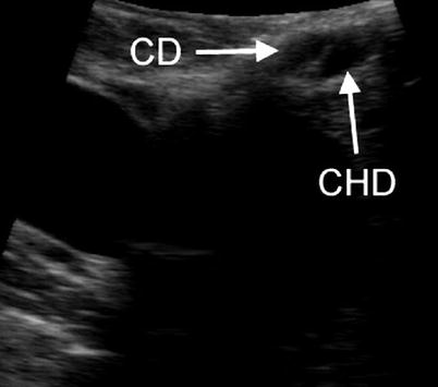
Fig. 13.8
The cystic duct (CD) and common hepatic duct (CHD) are imaged just as they join to form the common bile duct
After examining the cystic duct and cystic-CBD junction, the probe is slid further cephalad to visualize the common hepatic duct and right and left hepatic ducts. Often during this step the liver edge obstructs the probe when scanning through the epigastric trocar. If this occurs, the probe tip can be flexed to the right to create a longitudinal view of the hepatic ducts.
Umbilical Scanning Technique
In contrast to the transverse views seen when scanning through the epigastric trocar, the umbilical technique creates longitudinal images of the CBD. This allows for entire segments of the duct to be viewed simultaneously, and for this reason it is the preferred technique of many authors [12, 13]. However, scanning from an umbilical position requires removal and reinsertion of the laparoscope through the epigastric trocar. With the laparoscope viewing cephalad to caudad and the monitors positioned toward the head of the table, the movements of the probe are seen in a “mirror image” and are counterintuitive. This makes probe maneuvering awkward, especially for those new to the technique, and can therefore lengthen the time required to perform the examination. For this reason we prefer epigastric scanning, although surgeons should become proficient in both techniques as often a certain segment of the CBD cannot be viewed via the initial approach.
Umbilical scanning begins with the gallbladder released from both fundal and infundibular retraction. The probe is positioned over the liver and the gallbladder is visualized using segment V as an acoustic window. As in the epigastric technique, this view is used to adjust the sonographic image and the gallbladder is examined for stones and polyps. The probe is then moved medially over liver segment IV and the confluence of the hepatic ducts and hepatic arteries is visualized. Use of Doppler mode to identify arterial flow can be helpful in orienting the anatomy proximal to the branching of these structures.
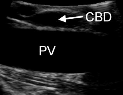
Once the common hepatic duct has been identified, it is examined for stones and sludge. With the probe entering through the umbilical trocar, the hepatic duct and CBD will be seen in longitudinal section (Fig. 13.9). The more proximal portion of the duct will appear toward the left side of the sonographic image using typical settings. In order to examine the entire width of the ducts, the probe is slowly rotated back and forth. Once a segment of the duct has been scanned in its entirety, the probe is slid caudad in order to scan distally. As the CBD enters the pancreatic head, its sonographic image will switch from longitudinal to oblique, as the duct curves to the patient’s right side and into the duodenum.
 Introduction: The Importance of Ultrasound in a Surgical Practice
Abdominal Ultrasound: Credentialing and Certification
Introduction: The Importance of Ultrasound in a Surgical Practice
Abdominal Ultrasound: Credentialing and Certification
 Getting Started
 Techniques in Laparoscopic and Intraoperative Ultrasound Guidance
 Abdominal Wall Anatomy, Pathology, and Intervention
 Percutaneous Ultrasound Guidance Techniques and Procedures


Related posts:
Introduction: The Importance of Ultrasound in a Surgical Practice
Abdominal Ultrasound: Credentialing and Certification
Getting Started
Techniques in Laparoscopic and Intraoperative Ultrasound Guidance
Abdominal Wall Anatomy, Pathology, and Intervention
Percutaneous Ultrasound Guidance Techniques and Procedures
Stay updated, free articles. Join our Telegram channel
Full access? Get Clinical Tree
