Fig. 3.1
(a) Diagram showing the structural parts of an ultrasound probe. (b) Figure showing various types of ultrasound probes
Piezoelectric materials
Backing material
Transducer housing
Matching layer
Piezoelectric Materials
The term piezoelectric is derived from the Greek words piezo, which means “to press,” and electron, which means “amber.” When these elements are deformed by pressure, a voltage is produced. These elements also convert mechanical energy of the returning ultrasound echoes on the probe to produce electrical voltages. These electrical voltages are transmitted to the monitor where images are formed. This technique of image production is called the “pulse-echo technique.” Echoes from anatomic structures correspond to the structures in a sonographic image.
Quartz, topaz, and amber are natural examples of piezoelectric materials, although various formulations of synthetic ceramics, such as lead zirconate titanate (PZT), are most commonly used in modern ultrasound probes as the transducer element. Some ceramics are made piezoelectric by placing the material in a strong electric field at high temperatures. Thus, these elements are heat sensitive, such that, if the critical temperature point (also called Curie point) is exceeded, then these elements would lose their piezoelectric properties. This is the reason why the ultrasound probes should never be autoclaved or exposed to extreme heat. These probes should be sterilized using either gas sterilization or high-level disinfection methods, making sure the electronic part is not soaked in the solution. The thickness of the crystal and the alternating voltage applied are factors that determine the frequency that the probe will create.
Backing (Damping) Material
Backing material is the material attached behind the piezoelectric material. This material is usually composed of metal powder and plastic epoxy resin. The function of this material is to reduce the vibrations of the piezoelectric material and, as a result, also reduce the pulse duration and spatial pulse length, thus improving resolution. In other words, ultrasound probe emits shorter pulses of ultrasound energy, so that more detailed high-quality images can be formed. However, the damping material causes a decrease in efficiency and sensitivity of the system by reducing the ultrasound amplitude. Some transducers intended for continuous wave Doppler do not have backing material, since pulses are not used. These transducers are more efficient because ultrasound energy is not lost during the damping process.
Transducer Housing
Transducer housing is usually composed of plastic and metal and encloses the piezoelectric material, damping material, and all the electrical connections. An intact transducer housing is important before attempting any sonographic examination, since broken transducer housings can cause serious injuries to the patient and the sonographer via electrical shock.
Matching Layer
Matching layer is the material that is on the face of the transducer located between the piezoelectric material and the patient. This layer matches the impedance difference between the solid probe and the body. This material has an intermediate impedance value and provides less reflection of the returning sound waves from the tissues to the transducer. Almost 80 % of the returning echoes would be reflected in the absence of this coating material since the transducer is solid and has an impedance value much higher than the tissues.
Since air has low impedance, a coupling medium, usually a gel, is required to avoid any contact of the ultrasound waves with air and to facilitate transmission of the sound waves to and from the tissues and the transducer. The gel also helps to diminish acoustic impedance mismatch between the skin and the transducer. Without the use of a coupling medium, most of the returning echoes would be reflected at the skin-transducer border and poor-quality images would be formed. Also, the inadequate use of coupling medium would result in artifacts that would cause an incorrect interpretation of the images.
Transducer (Probe) Types
Different types of transducers are needed for optimal imaging of the different structures in the body. Penetration of the ultrasound waves into tissues is inversely proportional to attenuation of the ultrasound signal. Attenuation is the weakening of the sound as it propagates. This concept is important as attenuation of the ultrasound energy limits the image depth and should be compensated by the ultrasound machine. This is why different transducers that generate ultrasound waves with different frequencies are needed for optimal imaging of the different parts of the body (Fig. 3.2).
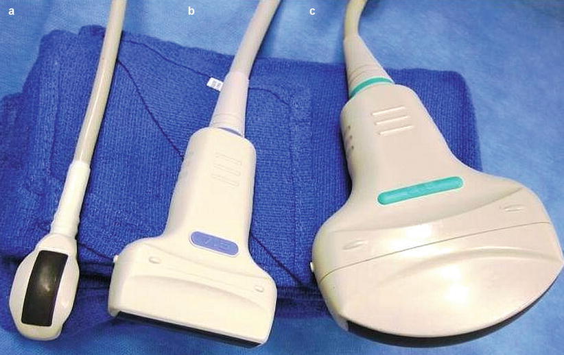
Fig. 3.2
Image depicting common probes which are used in different body regions with various frequency ranges. (a) Curvilinear array high-frequency small-parts probe. (b) Linear array high-frequency probe. (c) Curvilinear low-frequency probe
Attenuation is directly proportional to the frequency of the ultrasound transducer (see section “Attenuation” in Chap. 2). The higher the frequency of the probe, the more quickly the sound energy is lost over distance. High-frequency transducers are therefore unable to penetrate into deeper tissues but provide better image resolution. Inversely, transducers with lower frequency can penetrate into deeper tissues, however, with decreased resolution. Nevertheless, low-frequency transducers (e.g., 3.5–5 MHz) are preferable to do transabdominal scanning of the solid abdominal organs where depth of penetration is important. On the other hand, high-frequency transducers (e.g., 7.5–10 MHz) are ideal for thyroid and breast imaging, in addition to intraoperative ultrasound, where depth is less important and the image resolution is improved. The frequency of the probes can also be changed manually using the control panel of the ultrasound machine (Fig. 3.3a–c).
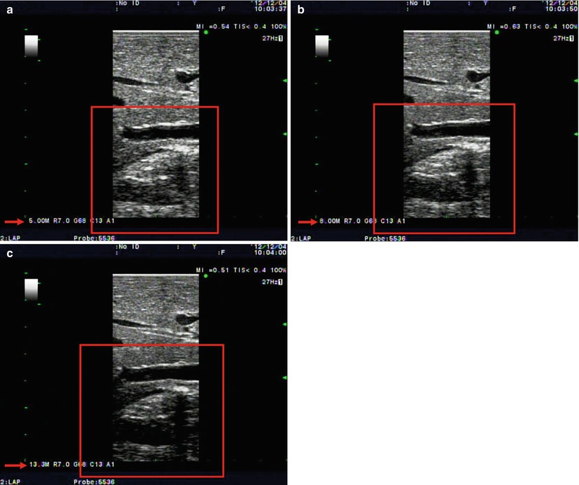
Fig. 3.3
(a–c) Figures showing ultrasound capture image of the liver parenchyma in (a) low, 5 MHz; (b) medium, 8 MHz; and (c) high, 13 MHz frequencies, respectively, adjusted by the surgeon intraoperatively. Note the changes in the image quality of the deep portion of liver scanned (red box) with different frequencies used
Mechanical Sector Probes
In mechanical sector-type transducers, a single crystal is attached to a rotating arm. Each time the probe sends a signal and receives the returning echo, a sector image is formed. This process is repeated so rapidly that formation of an image using one crystal is possible. These transducers are prone to breakage, since the motor of the arm rotates vigorously to obtain an image. Pie-shaped sector images are formed as a result of this type of scanning.
Endocavitary Probes
These probes also have a curved surface, and their unique extended design allows intracavitary evaluation of anatomic structures. Endocavitary probes provide wider views than curvilinear probes and also have higher frequency ranges (8–13 MHz). Thus, higher frequencies allow obtaining high-resolution images of close anatomic structures with a wider imaging area (see Chaps. 11 and 19 for more detail on endoluminal ultrasound).
Intraoperative and Laparoscopic Probes
Although the idea of intraoperative ultrasound dates back to the 1960s, this concept has not been accepted and widely used until the introduction of real-time B-mode ultrasound scanners. Furthermore, the introduction of laparoscopy and minimal invasive techniques to the field of surgery led to a wider usage of intraoperative ultrasound for precise resection margins and detection and preservation of vital anatomic structures during surgical interventions. Today, both linear and convex probes are available for open or laparoscopic scanning. The technique for the laparoscopic examination is more demanding, since the ultrasound probe needs to be introduced to the target organ site from a trocar and manipulated in a limited space with limited range of motion. There are rigid, flexible, and robotic probes designed for easy manipulation (Fig. 3.4a, b). These probes have a frequency range between 5 and 12 MHz, and they provide high-resolution images of the scanned organs. They do not need any coupling media for imaging.
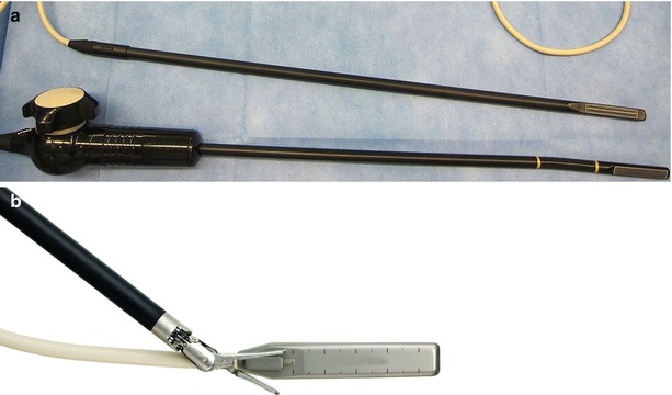
Fig. 3.4
(a, b) Photographs showing laparoscopic linear rigid and flexible (a) and drop-in robotic (b) probes
Array Types
Linear Array
Electronic scanning is achieved by arrays, which are transducer assemblies with multiple transducer elements. A linear array or linear-sequenced array consists of rectangular elements that are assembled in a straight line. A linear array forms rectangular images composed of many parallel vertical straight lines. This is achieved by pulses originating at different points across the surface of the array but traveling in the same vertical direction. This probe has higher frequencies ranging between 5 and 13 MHz, and as a result, it can be utilized for
Imaging of superficial soft tissueRelated posts:
 Introduction: The Importance of Ultrasound in a Surgical Practice
Abdominal Ultrasound: Credentialing and Certification
Introduction: The Importance of Ultrasound in a Surgical Practice
Abdominal Ultrasound: Credentialing and Certification
 Getting Started
 Techniques in Laparoscopic and Intraoperative Ultrasound Guidance
 Abdominal Wall Anatomy, Pathology, and Intervention
 Percutaneous Ultrasound Guidance Techniques and Procedures

Stay updated, free articles. Join our Telegram channel

Full access? Get Clinical Tree


